
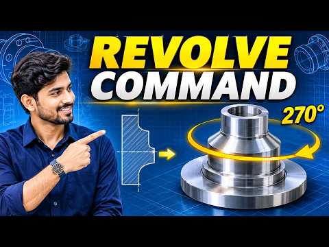
Are you getting started with computer-aided design (CAD) and looking to expand your 3D modeling skills? SolidWorks is one of the most powerful software programs available for engineers, designers, and hobbyists alike. One of the fundamental features every beginner must master is the Revolve command.
Before building rotational components like cylinders, pulleys, or handles, you need to start with a clean SolidWorks 2D sketch. In this step-by-step tutorial, we will walk you through how to turn a flat profile into a fully realized 3D object using the Revolve Boss/Base tool.
Step 1: Prepare Your Profile and Axis of Revolution
The key to a successful revolve feature lies in how you construct your initial drawing. Follow these essential steps:
- Create the Profile: Open a new part file, select a plane (such as the Front Plane), and start drawing. Build a precise SolidWorks 2D sketch that represents half of the cross-section of your final object. Ensure your profile forms a completely closed contour.
- Add a Centerline: The Revolve command requires an axis around which the geometry rotates. Draw a construction line or centerline along the intended axis of rotation.
Step 2: Executing the Revolve Command
Once your profile and centerline are properly defined, turning your design into 3D takes just a few clicks:
- Navigate to the Features tab on the top CommandManager.
- Click on Revolve Boss/Base.
- Select your centerline as the Axis of Revolution. SolidWorks will immediately generate a 3D preview of the rotated shape.
- Set your desired revolution angle (the default is 360 degrees for a full solid).
- Click the green checkmark to finish creating your 3D model.
Pro Tips for Clean 3D Revolves
- Keep Profiles Closed: A solid revolve requires a fully enclosed shape. If your geometry has open endpoints, SolidWorks may attempt to create a thin-feature shell instead of a solid body.
- Avoid Self-Intersecting Lines: Make sure your geometry does not cross over the centerline or overlap itself, as this causes rebuild errors.
- Focus on Constraints: Building a fully defined SolidWorks 2D sketch with accurate dimensions and geometric relations ensures your 3D model turns out precise every time.
Conclusion
The Revolve command is a powerful shortcut in 3D CAD modeling. By learning how to revolve a simple cross-section around an axis, you save time and keep your feature tree clean compared to using multiple extrusions. Open SolidWorks today, practice sketching your profile, and bring your 2D ideas to life in 3D!


