
Introduction to Heavy-Duty Industrial Modeling
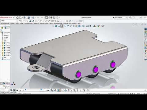
In the world of mechanical engineering, precision is everything. Whether you are designing small components or massive industrial equipment, the ability to translate a concept into a functional digital model is a vital skill. In this guide, we dive into Exercise 231: the 3D modeling and assembly of a Heavy-Duty Machinery Moving Skate. These skates are essential tools in factories, used to transport multi-ton equipment with ease and safety.
From Individual Parts to Full Assembly
The process begins with the creation of individual components. For a machinery moving skate, this involves modeling a robust steel frame, high-capacity rollers, and precision axles. Using SolidWorks, we utilize features like extruded bosses, revolved cuts, and fillets to ensure the structural integrity of every part.
Once the individual components are ready, the real magic happens in the Assembly environment. By applying standard mates such as concentric and coincident constraints, we can simulate the real-world movement of the rollers within the frame. This step is crucial for checking interference and ensuring that the final product will function correctly in a physical environment.
Precision Documentation with SolidWorks 2D Drawing
A 3D model is impressive, but for manufacturing purposes, clear documentation is the gold standard. Converting your complex 3D assembly into a detailed SolidWorks 2D drawing is a crucial step in the engineering workflow. This allows you to communicate dimensions, material specifications, and assembly instructions to the machine shop.
When generating a SolidWorks 2D drawing, it is important to include multiple views—such as top, front, and isometric—along with a Bill of Materials (BOM). This ensures that every nut, bolt, and roller is accounted for. Proper annotation within your SolidWorks 2D drawing helps prevent costly errors during the fabrication of the heavy-duty skate.
Enhancing Your Engineering Workflow
Mastering the transition from a 3D sketch to a finished assembly requires practice and patience. By following Exercise 231, you are not just learning how to use software; you are learning the logic of industrial design.
Focus on maintaining a clean feature manager tree and using descriptive names for your mates. This discipline makes it much easier when you eventually need to update your designs or export them for final production. With these skills, you’ll be well on your way to tackling even more complex mechanical challenges.


