
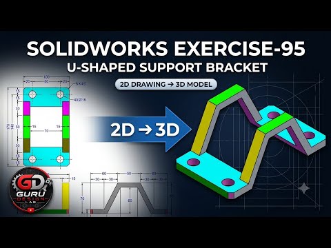
Converting technical blueprints into functional 3D CAD models is an essential skill for mechanical engineers, drafters, and product designers. If you want to enhance your computer-aided design capabilities, mastering SolidWorks 2D drafting is the perfect place to start. In this comprehensive tutorial based on Exercise 95 from Guru Design LAB, we explore how to translate a 2D engineering blueprint of a U-shaped support bracket into a precise 3D model.
Step 1: Analyzing the 2D Technical Drawing
Before jumping directly into feature creation, it is crucial to study the provided technical blueprint. Identifying primary orthographic views—such as front, top, and side projections—helps you determine the most efficient starting plane for your initial sketch.
For a U-shaped support bracket, carefully reviewing critical dimensions, hole locations, wall thickness, and geometric symmetry ensures that your SolidWorks 2D drafting foundation is completely accurate before extruding geometry into 3D space.
Step 2: Creating the Base Profile and Extrusions
Once you understand the dimensions, follow these core modeling steps in SolidWorks:
- Draw the Main Sketch: Select the front or top plane and sketch the primary U-shaped outline using precision line, arc, and constraint tools.
- Apply Dimensions & Relations: Add smart dimensions according to the 2D drawing to fully define the sketch.
- Extrude the Base: Use the Extruded Boss/Base feature to turn your flat 2D profile into a solid 3D bracket body.
- Cut Openings and Holes: Create secondary sketches on the bracket faces for mounting holes or slots, then apply the Extruded Cut tool.
- Add Finishing Details: Apply necessary fillets and chamfers to edges to mirror real-world manufacturing standards.
Why Practice Blueprint-to-3D Conversion?
Efficient parametric modeling relies heavily on strong fundamental drafting skills. Practicing SolidWorks 2D drafting with structured exercises builds design speed, improves blueprint reading accuracy, and eliminates costly modeling errors downstream.
Whether you are preparing for official SolidWorks certification (like CSWA or CSWP) or designing practical mechanical components, completing step-by-step exercises like this U-shaped support bracket will elevate your CAD workflow. Grab your blueprint, launch SolidWorks, and start converting your 2D ideas into 3D reality today!


