
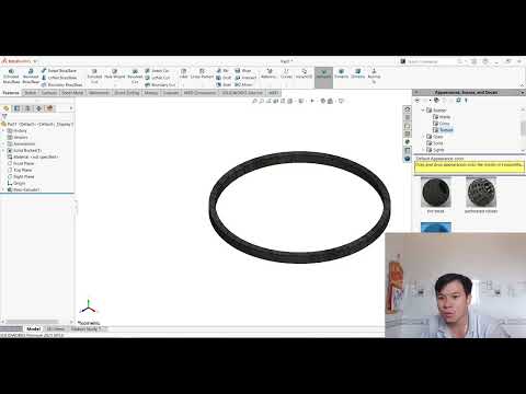
Designing a multi-cylinder engine is one of the ultimate tests of CAD skills for mechanical engineers and 3D designers. When working on complex machinery, mastering the SolidWorks 3D assembly process requires absolute precision—starting with individual components like the piston ring. In this tutorial installment of our four-cylinder engine series, we take a deep dive into modeling and preparing the piston ring for seamless integration.
Why the Piston Ring Matters in Mechanical Modeling
Though small in comparison to the crankshaft or engine block, the piston ring plays a critical role in internal combustion engines. It seals the combustion chamber, regulates oil consumption, and transfers heat from the piston to the cylinder wall. In CAD design, creating an accurate piston ring ensures proper clearances and realistic motion simulation during final component fitment.
Key Modeling Techniques in SolidWorks
To build a precise piston ring, begin with a clean 2D sketch referencing exact engine dimensions. Using essential features like Revolve Boss/Base or Extrude, you can define the ring’s cross-section and gap profile. Pay close attention to tolerance and dimensions, as even tiny discrepancies can disrupt the mating process when putting together your SolidWorks 3D assembly.
Key steps to keep in mind: - Setting up reference planes accurately for proper alignment. - Sketching the circular profile while accounting for the essential ring gap. - Applying proper smooth feature geometry to reflect real-world mechanical parts.
Integrating the Component into the Engine Project
Once individual component modeling is complete, the real magic happens in the assembly environment. Achieving a functional SolidWorks 3D assembly depends heavily on correct mating relationships. Aligning the piston ring within the piston grooves using concentric and parallel mates ensures structural accuracy and realistic component interaction.
Conclusion
Mastering small components like the piston ring builds a strong foundation for complex mechanical projects. By focusing on dimensional precision and proper mate conditions, you will streamline your workflow and elevate your overall CAD modeling capabilities. Continue practicing these fundamental techniques to take your 3D modeling skills to the next level!


