
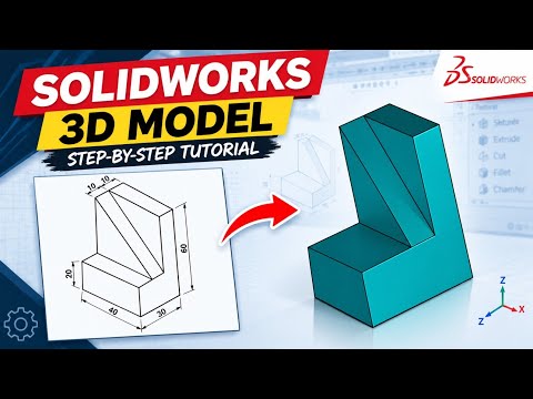
In the world of mechanical engineering and product design, the ability to transition seamlessly from a flat concept to a three-dimensional reality is a fundamental skill. SolidWorks remains the industry standard for this process, offering a robust suite of tools that turn complex ideas into functional parts. In this guide, we will explore the essential steps to transform a standard SolidWorks 2D drawing into a high-quality 3D mechanical component.
The Importance of a Solid Foundation
Every great 3D model begins with a precise sketch. Before you start using advanced features like "Revolve" or "Sweep," you must first master the art of interpreting your initial technical requirements. Accuracy at the sketching stage is non-negotiable; even a minor error in your SolidWorks 2D drawing can lead to significant assembly issues later in the design cycle. By ensuring all constraints and dimensions are fully defined, you create a parametric model that is easy to modify and update.
Step-by-Step Modeling Workflow
To create a professional-grade mechanical part, follow these systematic steps:
- Analyze the Blueprint: Start by studying the provided dimensions. Identify the primary features and determine which plane (Front, Top, or Right) is best suited for the base sketch.
- Sketching the Profile: Use the Sketch tools to replicate the geometry found in your SolidWorks 2D drawing. Focus on geometric relations like tangency, parallelism, and symmetry to keep the sketch stable.
- Applying 3D Features: Once the sketch is closed and fully defined, use the "Extruded Boss/Base" tool to add volume. From there, you can utilize "Extruded Cut" for holes and "Fillet" or "Chamfer" for finishing touches.
- Verification: Always cross-reference your 3D mass properties and dimensions back to the original source to ensure 100% accuracy.
Refining Your CAD Skills
Precision is what separates a hobbyist from a professional designer. As you practice more complex parts, you will find that the relationship between the 2D layout and the 3D geometry becomes second nature. Whether you are designing simple brackets or intricate engine components, the workflow remains the same: visualize, sketch, extrude, and refine.
By following this step-by-step approach, you will not only improve your modeling speed but also produce parts that are ready for manufacturing and prototyping. Happy modeling!


