
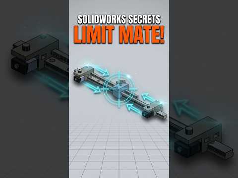
When designing mechanical assemblies, static positioning isn’t always enough. Whether you are working with sliding mechanisms, linear actuators, or simple constrained blocks, controlling the precise range of motion is essential for realistic design validation. Learning how to use advanced assembly tools like the Limit Distance Mate is a fantastic way to elevate your SolidWorks 3D modeling workflow.
What is a Limit Distance Mate?
In standard assembly design, a typical Distance Mate locks two entities at a fixed, unchanging distance. While useful, it doesn't represent real-world moving parts.
A Limit Distance Mate, on the other hand, allows components to move dynamically within a defined range. By setting both a maximum and minimum distance limit, you can precisely constrain the translation of parts—such as two sliding blocks—allowing motion without letting components separate too far or collapse into each other.
Step-by-Step: Applying a Limit Distance Mate
Setting up a Limit Distance Mate in your assembly is quick and intuitive:
- Open the Mate Tool: In your assembly environment, select the Mate option from the Assembly tab.
- Select Faces: Pick the two parallel faces or references (e.g., the opposing inner faces of two blocks) that dictate the movement boundaries.
- Access Advanced Mates: Scroll down the Mate PropertyManager panel and expand the Advanced Mates section.
- Select Limit Distance: Click on the Limit Distance icon.
- Set the Parameters: Input your target values for both the Maximum Distance (the furthest the components can move apart) and the Minimum Distance (the closest they can get). You can also define an initial distance for reference.
- Apply and Test: Click the green checkmark. Drag one of the blocks in the graphics area to watch it move smoothly within your designated range.
Why Limit Mates are Essential for Design Validation
Incorporating motion constraints into your models bridges the gap between basic CAD geometry and functional engineering. It helps prevent component interference during design reviews and ensures your mechanical motion matches real-world behavior. Mastering these techniques makes your SolidWorks 3D modeling projects significantly more accurate, professional, and presentation-ready.
By taking advantage of advanced mate features, you turn rigid assemblies into functional digital prototypes. Incorporate limit distance mates into your current project to streamline your SolidWorks 3D modeling process today!


