
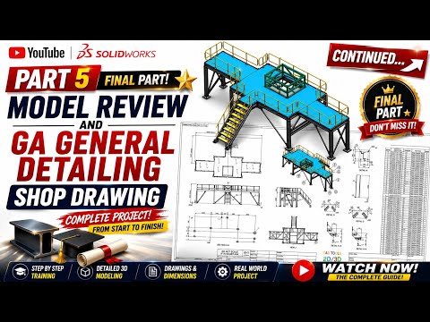
Completing a structural steel project requires moving seamlessly from a conceptual design to detailed, fabrication-ready documents. In the final phase of our structural detailing series, we take a complete steel platform project across the finish line—transitioning directly from a complex digital model to precise General Arrangement (GA) and shop drawings.
Thorough Review of the SolidWorks 3D Part
Before issuing drawings to the shop floor, conducting a comprehensive model review is critical. Inspecting every single SolidWorks 3D part within the assembly ensures that all beam connections, gusset plates, bolts, and welds align perfectly.
During this review stage, you must check for potential component interferences, verify structural clearances, and confirm that all weldments meet engineering specifications. Catching minor discrepancies in the virtual environment prevents costly rework and unexpected downtime during shop assembly.
Creating Accurate GA and Shop Drawings
Once the 3D model passes inspection, the next step is extracting high-quality production documentation. General Arrangement (GA) drawings provide the macroscopic view needed for field erection, while detailed shop drawings break down each individual structural member.
When converting your finalized SolidWorks 3D part models into 2D production sheets, pay close attention to:
- Dimensional Accuracy: Ensure all hole centers, cut lengths, and bevel angles are explicitly detailed.
- Bill of Materials (BOM): Generate automated BOM tables to streamline material procurement and component tracking.
- Annotation & Welding Symbols: Include clear welding notes, material grades, and surface treatment requirements for fabricators.
Streamlining the Path to Fabrication
Mastering the full workflow from a raw 3D model to ready-to-use shop drawings is what sets expert CAD technicians apart. By properly structuring each SolidWorks 3D part, managing sub-assemblies efficiently, and generating precise drawing packages, you bridge the gap between design engineering and physical construction.
Whether you are working on industrial platforms, access stairways, or heavy steel frames, applying these final drawing output steps guarantees a smooth transition from the screen to the steel yard. Take these proven CAD techniques into your next structural modeling project and build with total confidence!


