
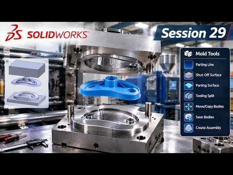
Designing molds for complex plastic parts requires precision, accuracy, and an efficient software workflow. In modern manufacturing, SolidWorks 3D mold design stands out as an industry standard, empowering engineers to transition seamlessly from a 3D part model to a production-ready mold tool.
Mastering Core and Cavity Extraction
Extracting the core and cavity is the foundation of any successful tooling project. Within SolidWorks, specialized Mold Tools simplify this complex geometric operation. The process begins with a thorough draft analysis to ensure the plastic component can cleanly eject from the mold without causing structural defects or surface drag marks.
Once the draft analysis is verified, parting lines and parting surfaces are established. These critical elements split the mold volume into two main components: the core (which forms the internal shape) and the cavity (which forms the external shape). By leveraging the native tooling features in SolidWorks, designers can accurately generate shutdown surfaces to seal off open holes before executing the final tooling split.
Best Practices for Efficient Mold Tooling
To achieve high-quality results in SolidWorks 3D mold design, careful preparation during the initial setup is non-negotiable. Here are essential best practices to streamline your CAD workflow:
- Apply Proper Shrinkage Allowance: Always account for material contraction by applying a scale feature to the part before generating mold blocks.
- Identify Undercuts Early: Use undercut analysis to locate geometry that prevents straight-pull ejection, allowing you to plan for side-actions or lifters.
- Maintain Clean Surface Geometry: Ensure knitted surfaces are watertight and free of topological errors to prevent failures during the tooling split phase.
Streamline Your Manufacturing Workflow
Understanding the end-to-end workflow of SolidWorks 3D mold design allows CAD professionals to minimize costly physical prototyping errors, lower production expenses, and accelerate time-to-market. By following a structured approach to core and cavity extraction, engineers can produce precise, high-performing mold assemblies ready for modern injection molding processes.


