
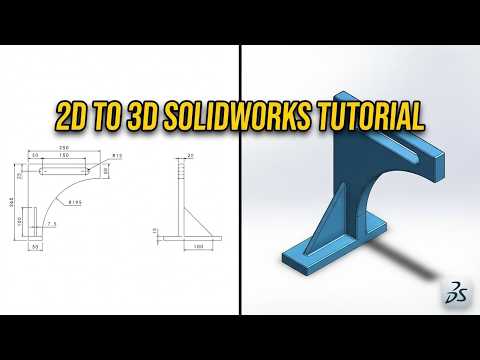
Transitioning from flat blueprints to dynamic 3D models is a foundational skill for any aspiring engineer or product designer. In our latest tutorial, we dive deep into a subscriber-requested challenge: converting a complex SolidWorks 2D drawing into a fully realized, three-dimensional mechanical bracket.
Whether you are a student or a professional looking to sharpen your workflow, understanding how to interpret technical dimensions and translate them into features is key to mastering CAD software.
Starting with the Blueprint
The process begins with a detailed analysis of the initial SolidWorks 2D drawing. Before opening a new part file, it is essential to identify the primary views—top, front, and side—to determine the best plane for your first sketch. In this exercise, we focus on a complex bracket that requires a mix of linear extrusions, precise hole placements, and specific fillets. By identifying the "parent" features of the design first, you can save significant time during the modeling phase.
Step-by-Step Conversion Strategy
To move from 2D to 3D efficiently, we follow a structured workflow: 1. Sketching the Base: Using the dimensions provided in the drawing, we create the primary profile. We emphasize using "Fully Defined" sketches to ensure the model remains robust during future edits. 2. Adding Depth: We utilize the Extruded Boss/Base tool to bring the 2D shapes into the 3D workspace. 3. Refining the Geometry: Once the bulk of the bracket is created, we move on to secondary features such as countersunk holes, slots, and ribs. 4. Applying Finishing Touches: Fillets and chamfers are added last to replicate the exact specifications found on the original technical sheet.
Why Practice with 2D Drawings?
Many modern designers rely heavily on "designing on the fly," but being able to accurately recreate a part from a SolidWorks 2D drawing is a vital industry skill. It ensures you can work with legacy data, collaborate with manufacturing teams, and pass professional certification exams.
By following this tutorial, you will gain the confidence to tackle even the most intricate mechanical drawings. If you’re ready to level up your design game, grab your mouse, open your workstation, and let’s start modeling!


