
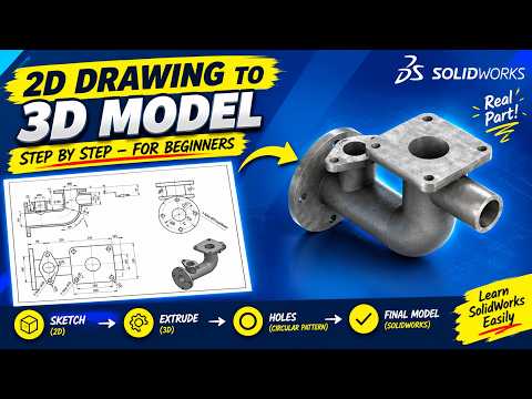
Transitioning from a flat 2D technical drawing to a fully realized 3D model is one of the most essential skills for any CAD designer or mechanical engineer. Whether you are building simple mechanical components or intricate machinery, mastering the end-to-end workflow in SolidWorks allows you to turn abstract blueprints into production-ready designs. In this guide, we break down how to take your 2D drawings and transform them into a fully functional SolidWorks assembly.
Step 1: Mastering the 2D Sketch
Every great 3D model starts with a clean, fully defined 2D sketch. When analyzing your technical drawing, identify the primary base feature of your part. Focus on establishing accurate dimensions, relations, and geometric constraints right from the start. By keeping your initial sketches simple and fully defined, you create a robust design intent that makes future modifications quick and error-free.
Step 2: Extruding and Detailed Feature Modeling
Once your base sketch is ready, use SolidWorks features such as Boss Extrude, Revolve, and Cut Extrude to construct your 3D geometry. As your part takes shape, add secondary details like fillets, chamfers, and threaded holes using the Hole Wizard. Working parametrically ensures that any modification to your original sketch dimensions will automatically update your 3D part without causing errors downstream.
Step 3: Bringing Components Together in a SolidWorks Assembly
After modeling each individual component, the next step is combining them in the assembly environment. Building a precise SolidWorks assembly relies on applying proper mates—such as concentric, coincident, and distance constraints. Mating your parts correctly not only anchors them accurately in 3D space but also simulates realistic mechanical motion, allowing you to evaluate component relationships effectively.
Key Best Practices for CAD Success
- Organize Your Feature Tree: Rename features and parts logically to keep your design tree clean and easy to navigate.
- Run Interference Detection: Use built-in evaluation tools to identify overlaps and ensure every part fits seamlessly within the final SolidWorks assembly.
- Verify Design Intent: Double-check your 3D model dimensions against the original 2D drawing to guarantee manufacturing accuracy.
Conclusion
Modeling complex projects in SolidWorks does not have to be intimidating. By breaking the process down into sketching, feature creation, and systematic assembly mating, you can tackle virtually any mechanical CAD project with complete confidence. Start practicing this workflow today to streamline your engineering design process!


