
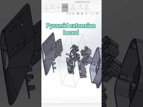
In modern product design, mastering 3D CAD software is crucial for converting creative concepts into functional physical models. One fascinating exercise for CAD enthusiasts is building non-traditional geometric hardware, such as a pyramid extension board. Utilizing a SolidWorks 3D assembly workflow allows designers to bring unique shapes to life while ensuring precise component fit and realistic aesthetics.
Step-by-Step Approach to Pyramid Extension Board Design
Creating a pyramid-shaped power extension board requires a combination of precise part modeling and strategic assembly mates. Here is how you can approach this project:
- Individual Component Modeling: Start by modeling the core parts separately in SolidWorks. This includes the main multi-faceted pyramid casing, individual power socket modules, internal connection plates, switch cutouts, and the flexible power cord.
- Establishing Mates and References: Once the parts are ready, open a new assembly file. Insert the primary pyramid base as a fixed component. Gradually add socket inserts and electrical contacts using standard mates—such as coincident, concentric, and distance mates—to lock components securely into place.
- Detailing and Material Appearance: Apply realistic textures and materials, such as matte plastic for the outer body and brass or copper for the internal electrical prongs, to achieve a professional visual result.
Advantages of Using SolidWorks for Complex Assemblies
Executing a SolidWorks 3D assembly offers several distinct advantages over traditional drafting methods:
- Interference Detection: Easily check for overlapping geometries or clearance issues inside compact enclosures before sending designs to 3D printing or manufacturing.
- Flexible Revisions: Editing a single part automatically updates the entire model, saving valuable time during design iterations.
- Realistic Visualization: High-quality rendering tools allow engineers to present fully assembled, realistic product concepts to prospective clients or technical teams.
Elevate Your CAD Skillset Today
Designing items with unique geometry, like a pyramid extension board, pushes your creative boundaries while strengthening core CAD fundamentals. Whether you are a student, hobbyist, or professional engineer, practicing the SolidWorks 3D assembly process on varied projects will significantly boost your design efficiency and technical proficiency. Try building your own multi-socket extension board today to master custom component mating and spatial layout design!


