
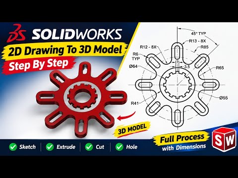
In modern engineering and mechanical design, converting a static blueprint into an interactive 3D model is a vital skill. While traditional blueprints contain all necessary dimensions, creating a 3D model allows designers to visualize parts clearly, perform accurate simulations, and streamline manufacturing processes. Mastering SolidWorks 2D drafting and learning how to transition those detailed line drawings into parametric 3D geometry is one of the best ways to elevate your CAD workflow.
Step-by-Step Guide: From 2D Blueprint to 3D Model
1. Analyze the Engineering Blueprint
Before opening your software, carefully review the fully dimensioned 2D drawing. Identify the primary orthogonal views—front, top, and side—and determine which view provides the most defining profile. Choosing the right view for your initial sketch will significantly simplify your modeling process.
2. Create the Base 2D Sketch
Open a new part document in SolidWorks and select the corresponding plane (such as the Front Plane). Using fundamental SolidWorks 2D drafting tools like lines, arcs, circles, and Smart Dimensions, carefully recreate the main profile of the component. Always aim for a "Fully Defined" sketch status by adding precise dimensional values and geometric relations.
3. Transform 2D Geometry into 3D Solid
Once your base sketch is fully defined, navigate to the Features tab and select the Extruded Boss/Base command. Input the exact depth or thickness provided in the drawing dimensions to transform your flat 2D sketch into a solid 3D feature.
4. Add Secondary Features and Detailing
With the primary solid body formed, select specific faces to draw additional features like cutouts, holes, or ribs. Use tools such as Extruded Cut, Fillet, and Chamfer to incorporate every detail from the engineering blueprint until the 3D model perfectly mirrors the 2D dimensions.
Why Master 2D to 3D CAD Workflows?
Fluidly transitioning from SolidWorks 2D drafting to complete 3D modeling helps eliminate design mistakes, improves accuracy, and saves valuable engineering time. Whether you are converting legacy paper drawings into modern CAD files or building parts from customer specifications, following a structured step-by-step approach ensures accurate and high-quality results every time.


