
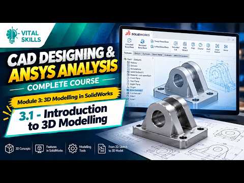
Introduction to 3D Modelling
Every complex engineering component—from a simple household bracket to an intricate automotive engine block—begins its life as a flat, two-dimensional draft. In modern Computer-Aided Design (CAD), mastering the step-by-step transition from flat geometry to spatial volume is fundamental. Learning how to create a precise SolidWorks 2D sketch serves as the vital foundation for all your advanced 3D modeling and engineering analysis workflows.
The Foundations of 3D CAD Design
3D CAD design relies on parametric feature-based modeling. Instead of sculpting a 3D shape directly in free space, designers construct 3D parts by adding depth to two-dimensional profiles.
When you understand the basic mechanics of how geometry behaves on a flat plane, adding a third dimension becomes intuitive. A well-constructed profile prevents errors later in the design process, making downstream tasks—such as finite element analysis (FEA) in ANSYS or preparing files for 3D printing—significantly smoother.
The Core Workflow: Converting 2D Profiles to 3D Parts
The transformation from a flat drawing to a solid 3D part follows a clear, logical workflow:
- Selecting the Reference Plane: Every design starts by picking an initial sketching environment, typically the Front, Top, or Right plane.
- Drafting the Profile: You draw lines, arcs, circles, and rectangles to form the cross-section of your component. When creating your SolidWorks 2D sketch, it is crucial to apply proper geometric relations (such as parallel, perpendicular, or tangent) and smart dimensions to fully define the geometry.
- Applying 3D Features: Once the profile is closed and fully defined, you apply a 3D feature operation. The most common feature is an Extruded Boss/Base, which pulls the flat profile along a straight vector to create volume. Other techniques include Revolves around an axis, Sweeps along a path, or Lofts between multiple profiles.
Best Practices for Better 3D Modeling
To ensure your CAD models remain easy to edit and modify, keep these best practices in mind: * Keep Sketches Simple: Avoid overly complicated profiles in a single drawing. Build your model using multiple simple features rather than one complex layout. * Fully Define Your Work: Always ensure your geometry is fully constrained with dimensions and relations to avoid accidental movement later. * Design for Intent: Before drawing your initial SolidWorks 2D sketch, consider how the final part will be manufactured or analyzed.
Final Thoughts
Mastering 3D modeling is all about taking consistent, controlled steps. By understanding how flat profiles turn into volumetric shapes, you gain the confidence to tackle complex engineering designs and advanced simulations. Start practicing today, and watch your 2D ideas take shape in 3D!


