
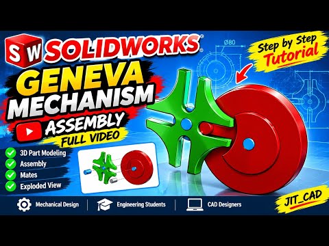
The Geneva mechanism, also known as the Maltese cross, is a classic mechanical device used to translate continuous rotational motion into intermittent rotary motion. Originally vital in early film projectors and mechanical timepieces, it remains a fundamental concept in mechanical engineering design. Whether you are a student or an experienced CAD designer, learning how to model this mechanism is a fantastic way to elevate your engineering skills. In this tutorial, we will guide you through creating a dynamic SolidWorks 3D assembly from start to finish.
Understanding the Geneva Mechanism
The mechanism consists of two main rotating components: a driving wheel equipped with a pin and a driven wheel featuring symmetrical slots. As the driving wheel rotates continuously, the pin engages one of the slots, advancing the driven wheel by a precise step before locking it into place until the next cycle. Capturing this mechanical movement in CAD requires accurate sketching dimensions and proper mating strategy.
Key Steps to Build Your Assembly
Creating a functional SolidWorks 3D assembly requires a clear, structured workflow. Here is a breakdown of the modeling process:
- Individual Part Modeling: Begin by sketching and extruding the core components—the Geneva wheel, the drive wheel with its indexing pin, and the stationary base plate. Precision in center-to-center distances is critical for accurate operation.
- Component Placement and Mating: Import all parts into the assembly space. Fix the base plate and apply standard mates, such as concentric and coincident mates, to align the rotating axes.
- Simulating Mechanical Motion: To mimic physical interaction, utilize mechanical mates or apply contact sets between the driving pin and the slotted wheel. This ensures smooth engagement without physical interference.
Benefits of Practicing CAD Assemblies
Taking on real-world mechanical projects in CAD refines your parametric design skills and sharpens your spatial awareness. Developing a fully constrained SolidWorks 3D assembly helps you master advanced dynamic mates, evaluate mechanical clearance, and perform motion simulation with confidence.
Ready to test your modeling expertise? Follow our step-by-step tutorial video, grab your dimensions, and start building your own functional mechanical assembly today!


