
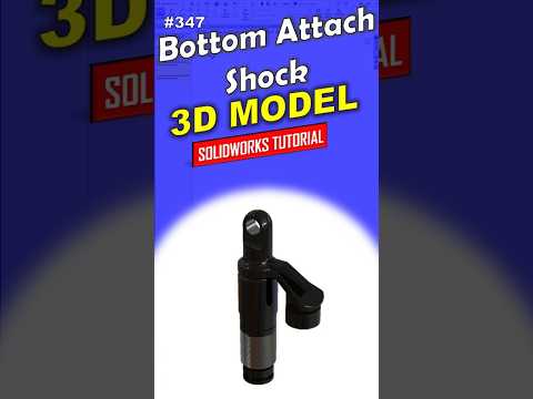
Are you looking to elevate your CAD skills and create professional-grade mechanical components? Designing detailed engineering parts, such as a bottom attach shock absorber, is one of the best ways to practice precision and efficiency. Whether you are a complete beginner or an aspiring mechanical designer, mastering SolidWorks 3D modeling is a crucial step in your CAD journey.
In this guide, we break down the process of creating a robust shock absorber attachment using a clean, step-by-step workflow.
Why Master SolidWorks 3D Modeling?
SolidWorks is an industry-standard parametric software used by engineers and product designers worldwide. From automotive design to consumer products, knowing how to transform 2D conceptual sketches into precise 3D geometry is an invaluable skill.
By taking a structured approach to SolidWorks 3D modeling, you ensure that your design intent is maintained. This makes your feature tree clean, organized, and easy to modify whenever engineering changes occur down the line.
Key Steps to Model a Bottom Attach Shock
Creating a complex mechanical component requires systematic planning. Here is how you can approach the build:
- Set Up Base Sketches: Begin by selecting the appropriate reference plane. Draw the main outer profile of the shock attachment using smart dimensions and geometric relations to secure its shape.
- Generate Main Features: Use parametric tools like Boss-Extrude or Revolve to convert your 2D geometry into a solid 3D foundation.
- Incorporate Mounting Features: Utilize tools such as Cut-Extrude and the Hole Wizard to add precise mounting holes, cutouts, and attachment points required for assembly.
- Apply Finishing Touches: Finish the part by applying fillets and chamfers to sharp edges. This not only enhances visual appeal but also simulates real-world stress reduction for manufactured parts.
Pro Tips for CAD Beginners
- Keep Sketches Fully Defined: Always ensure your sketch geometry turns black (fully defined) before creating a feature to avoid unexpected design shifts.
- Order Features Logically: Focus on primary structural shapes first before moving on to secondary cuts and cosmetic fillets.
- Practice Regularly: The fastest way to boost your SolidWorks 3D modeling speed is to practice replicating everyday mechanical components.
Conclusion
Building detailed 3D parts does not have to be intimidating. By following a consistent, professional method, you can build confidence and tackle complex CAD projects with ease. Open your software, create a new part file, and start designing today!


