
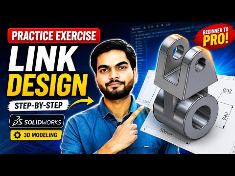
Elevate Your Engineering Skills with Mechanical Modeling
In the world of modern engineering, the ability to transform a conceptual sketch into a functional digital prototype is an essential skill. Whether you are a student just starting out or a professional looking to sharpen your toolkit, mastering SolidWorks 3D is a critical step toward becoming a proficient designer. This tutorial focuses on a core mechanical engineering component: the mechanical link.
Mechanical links are fundamental parts used in various assemblies to transmit motion and force. By following this exercise, you will gain a deeper understanding of how to manage geometric constraints and feature-based modeling to create parts that are both accurate and easy to modify.
From 2D Sketch to 3D Reality
Every great design begins with a solid foundation. In this exercise, we start by creating a precise 2D sketch on the appropriate plane. This involves using basic entities such as circles, arcs, and lines to define the overall shape of the link. The key here is to ensure the sketch is "Fully Defined" using smart dimensions and geometric relations like tangency and symmetry.
Once the profile is set, we move into the actual SolidWorks 3D environment. By applying the Extruded Boss/Base feature, we give the sketch its third dimension. This step is where you learn to manage material thickness and mid-plane extrusions, which are vital for maintaining symmetry in complex assemblies.
Refining the Mechanical Link
A raw extrusion is rarely a finished product. To make the mechanical link functional and realistic, we must add specific features. This includes: * Hole Wizard: Creating precise mounting points for pins or shafts. * Fillets and Chamfers: Adding rounds to edges to reduce stress concentrations and improve aesthetics. * Material Assignment: Choosing the right alloy to simulate weight and physical properties.
This hands-on approach to SolidWorks 3D modeling helps you understand the relationship between different design features. By the end of this tutorial, you will have a robust 3D model ready for stress analysis or 3D printing. Practice is the only way to master CAD, so dive in and start building your mechanical library today!


