
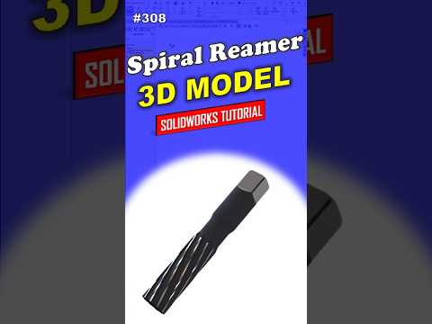
Precision engineering relies heavily on accurate CAD models, especially when designing specialized cutting tools like reamers. Spiral reamers are essential tools used in metalworking to enlarge and finish previously drilled holes with extreme accuracy. If you want to refine your 3D design capabilities, learning how to build complex industrial components in SolidWorks is an excellent way to advance your engineering skillset.
In this guide, we will explore a step-by-step professional workflow for modeling a 308 spiral reamer from scratch.
Understanding the Geometry of a Spiral Reamer
Before jumping into the software, it helps to break down the key anatomical features of a spiral reamer: - Shank: The cylindrical portion secured by the machine holder. - Flute Section: The main cutting portion featuring twisted grooves. - Spiral Flutes: Helical channels designed for smooth material removal and efficient chip evacuation.
Because of these helical grooves, creating this tool requires advanced feature operations beyond standard extrusions.
Step-by-Step Modeling Workflow
-
Create the Main Cylindrical Body
Start a new part file and draw the main profile on the Front Plane. Use a Revolve or Boss-Extrude feature to form the solid body representing the shank and the cutting length. -
Generate the Helical Guide Path
Select the top face of the cutting section, draw a circle matching the outer diameter, and insert a Helix/Spiral curve. Adjust the pitch and revolution parameters to match your desired flute twist rate. -
Sketch the Flute Profile
Create a reference plane perpendicular to the start point of the helix. On this plane, sketch the cross-sectional profile of the cutting edge, keeping realistic rake and relief angles in mind. -
Perform a Swept Cut
Utilize the Swept Cut feature by selecting your flute sketch as the profile and the helix as the path. This operation carves out the first spiral groove along the tool length. -
Apply a Circular Pattern
Use the Circular Pattern tool to duplicate the swept cut around the main central axis, creating an evenly spaced set of cutting flutes. -
Add Precision Details
Apply chamfers to the leading edge for proper entry geometry, and add fillets to reduce sharp stress concentration points along the tool shank.
Elevate Your Mechanical CAD Skills
Building industrial tools in SolidWorks helps beginners transition into professional parametric design. By mastering helical curves, swept cuts, and pattern features, you establish a strong foundation for tackling complex mechanical assemblies.
Practice this step-by-step process to build your design confidence and take your SolidWorks expertise to the next level!


