
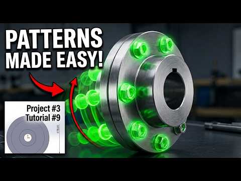
Flange couplings are fundamental mechanical components used to connect two rotating shafts, ensuring smooth power transmission in machinery. Whether you are a beginner CAD enthusiast or an experienced mechanical engineer, knowing how to efficiently build a SolidWorks 3D part like a flange coupling is an essential skill. In this guide, we will walk you through modeling a detailed flange coupling while leveraging the powerful Circular Pattern feature to streamline your workflow.
Creating the Base Geometry
To start building your flange coupling, open a new part document and create a sketch on the Front Plane. Draw concentric circles representing the shaft bore, outer hub, and flange outer diameter. Using the Extruded Boss/Base tool, extrude the sketch to form the main solid cylindrical body. At this stage, you can also add keyway cuts to ensure your model aligns with real-world mechanical specifications.
Harnessing the Circular Pattern Tool
One of the most critical steps in designing this SolidWorks 3D part is creating the bolt holes across the flange face. Sketching each hole individually is time-consuming and inefficient. Instead, you only need to model a single hole using the Extruded Cut tool.
Once the initial hole is created, follow these quick steps: 1. Navigate to the Features tab on the command manager. 2. Click the arrow under Linear Pattern and select Circular Pattern. 3. Choose the central cylindrical face or axis as your pattern reference. 4. Select the bolt hole cut as the feature to pattern. 5. Set the instance count (e.g., 4 or 6) and check Equal Spacing.
SolidWorks will instantly replicate the feature around the entire circumference with perfect geometric accuracy.
Finishing Touches and Best Practices
To complete your model, apply chamfers to the shaft entry points and fillets to the internal sharp corners. This not only improves stress distribution in real-world applications but also gives your model a polished, professional appearance. Utilizing parametric tools like the Circular Pattern keeps your feature tree organized and easy to modify whenever design changes are required.
Conclusion
Mastering parametric features makes creating any complex SolidWorks 3D part fast, accurate, and repeatable. Apply these step-by-step techniques to your next CAD project and take your 3D modeling skills to the next level!


