
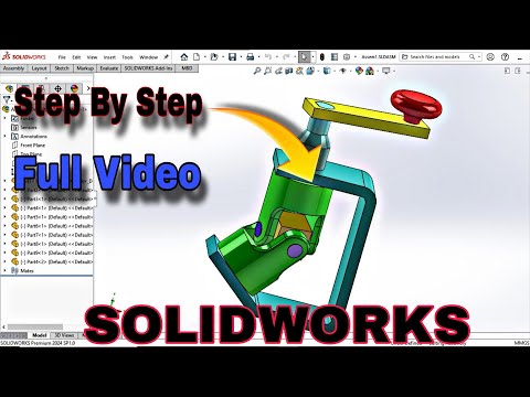
Universal joints—also known as universal couplings or Cardan joints—are fundamental mechanical components used to transmit rotary motion between two non-parallel shafts. Whether you are an engineering student or a professional CAD designer, mastering the creation of a SolidWorks 3D assembly for a universal joint is a crucial milestone in building your technical modeling skills.
In this step-by-step guide, we break down the process of modeling each individual part and assembling them seamlessly in SOLIDWORKS to ensure proper mechanical motion and physical accuracy.
Understanding the Key Components
Before applying assembly constraints, it is essential to model the core components that make up a functional universal coupling joint:
- Forks (Yokes): Two U-shaped components that attach to the driving and driven shafts.
- Center Block (Spider): The central cross-shaped connector that joins the two forks together.
- Pins and Keys: Fasteners designed to hold the assembly intact while permitting smooth rotational movement.
Step-by-Step Assembly Workflow
Creating a dynamic, functional mechanism requires precise geometry and correct mating relationships. Here is the general workflow to construct your project:
- 1. Part Modeling: Begin by sketching and extruding each individual part. Pay close attention to hole clearances, pin diameters, and shaft alignment to prevent interference during motion simulation.
- 2. Inserting Components: Open a new assembly file and insert the center block as your reference component. Add the driving and driven forks into the workspace.
- 3. Applying Mates: Use concentric mates to align the cylindrical holes of the forks with the center block arms, followed by coincident mates to control axial translation. Setting up a proper SolidWorks 3D assembly ensures that rotational forces transfer accurately across angled shafts without crashing.
Why Master Universal Joint Assemblies?
Building a universal joint is more than just a visual exercise—it is a practical lesson in mechanical kinematics. By completing a complex SolidWorks 3D assembly, you sharpen your ability to apply mechanical mates, detect physical interferences, and analyze dynamic motion in real-time engineering applications.
Ready to take your 3D modeling skills to the next level? Follow along with our complete step-by-step video tutorial, launch SOLIDWORKS, and start building your own universal joint model today!


