
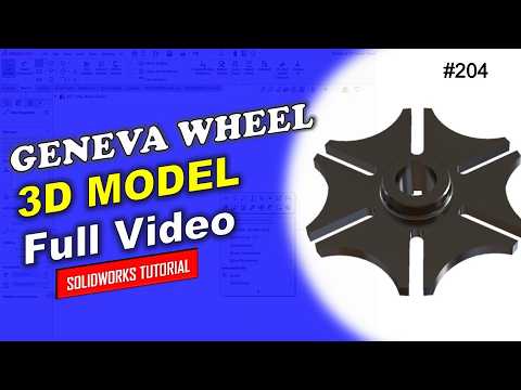
The Geneva Wheel, also known as the Geneva drive, is a classic mechanical component widely used to translate continuous rotational motion into intermittent rotary motion. Whether you are working on modern automated machinery or studying kinematic design, learning how to model this essential mechanism is a fantastic way to sharpen your engineering skills.
In this tutorial, we walk you through designing a 204 Geneva Wheel from scratch. Designed for beginners and intermediate CAD enthusiasts alike, this guide demonstrates a clean, professional approach to 3D modeling using SolidWorks.
Understanding the Geometry of a Geneva Mechanism
Before jumping into sketching, it helps to understand how the mechanism operates. The assembly typically consists of a driving wheel with a pin and a driven wheel featuring radial slots. To ensure smooth power transmission without binding, precise geometric constraints and exact dimensions are required. Building precision mechanical components in SolidWorks relies heavily on establishing accurate center distances, slot widths, and locking arcs right from the initial sketch.
Core Steps to Model the Geneva Wheel
Creating the 204 Geneva Wheel involves several fundamental parametric modeling techniques:
- Base Sketching: Start by establishing the main outer diameter and center hub profiles on a standard plane using precise parametric relations.
- Extruding Features: Use basic extrusion tools to give your 2D sketch its primary 3D base thickness.
- Drafting Slots and Cutouts: Sketch the locking arc and single radial slot geometry with exact tangency constraints. Apply a cut feature to create the drive slot.
- Applying Circular Patterns: Instead of sketching every slot individually, leverage feature-based circular patterns to replicate the cutouts symmetrically around the central axis.
- Finishing Touches: Add clean fillets and chamfers to remove sharp edges, preparing the final part for motion assembly or 3D printing.
Why Practice Mechanical Modeling?
Mastering complex mechanical parts requires consistency and proper sketching habits. By following structured workflows, you learn to create fully defined sketches that make future design modifications fast and error-free.
Elevating your mechanical design skills and mastering 3D design using SolidWorks will help build a strong foundation for your engineering portfolio. Follow along with the step-by-step video process to build your model today!


