
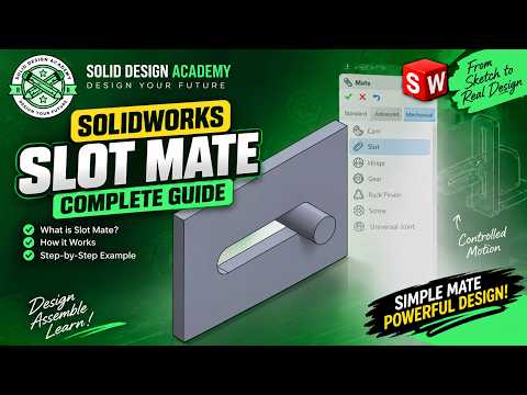
Designing dynamic mechanical assemblies requires precise constraint management. One of the most effective tools for defining constrained, real-world motion between components is the Slot Mate. Whether you are building complex machinery or simple mechanical linkages, mastering this feature in SolidWorks will drastically improve your assembly workflow.
What is the Mechanical Slot Mate?
The Slot Mate falls under the Mechanical Mates category. It allows you to align a cylindrical pin, bolt, or axis inside a straight or curved slot. Instead of relying on multiple standard mates (like concentric and distance mates) that can over-constrain or clutter your feature tree, a single Slot Mate controls the movement smoothly along the slot path.
Key Constraint Options
When setting up a Slot Mate, you have flexible options to control how the pin behaves inside the slot:
- Free: The pin can move freely along the entire length of the slot without escaping the boundaries.
- Center in Slot: The pin is locked directly in the exact middle of the slot length.
- Distance / Percentage: You can specify a precise offset distance or percentage from one end of the slot to limit movement.
How to Apply a Slot Mate Step by Step
- Open Your Assembly: Ensure both the slot component and the pin component are inserted into your assembly workspace.
- Access the Mate Tool: Click on the Mate icon located in the Assembly tab.
- Select Mechanical Mates: Expand the Mechanical Mates section in the PropertyManager and select Slot.
- Make Your Selections: Click the interior face of the slot and the cylindrical surface of the pin or bolt.
- Choose Constraint Type: Select your desired motion behavior (Free, Centered, Distance, or Percentage).
- Confirm and Test: Click the green checkmark to finalize the mate, then drag the component to test its realistic motion.
Conclusion
By incorporating mechanical constraints correctly, your 3D models will mirror physical reality much more accurately. Learning how to properly configure these features in SolidWorks saves engineering time, prevents mate errors, and ensures seamless design validation. Try implementing the Slot Mate in your next assembly project to streamline your 3D CAD workflow!


