
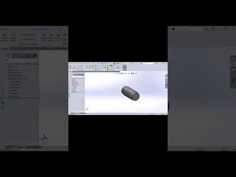
Designing mechanical components is a fundamental skill for any CAD designer or mechanical engineer. Among these components, drive shafts are essential elements used in power transmission systems across countless industries. In this guide, we will walk you through creating a standard cylindrical shaft using SolidWorks, utilizing simple 3D modeling features that streamline your workflow.
Step 1: Setting Up the Base Profile
To begin modeling your shaft, open a new part file and select a suitable sketching plane, such as the Front Plane. Start by drawing a horizontal center-line to act as your axis of revolution. Next, sketch half of the shaft’s stepped profile using basic line tools. Adding precise smart dimensions at this early stage ensures your sketch remains fully defined, making future modifications fast and predictable.
Step 2: Generating the 3D Geometry
Once your 2D cross-section is fully dimensioned, switch to the Features tab and select the Revolved Boss/Base command. By revolving the sketch 360 degrees around your center-line, you instantly convert your 2D profile into a solid 3D cylindrical body. Utilizing revolved features in SolidWorks is significantly more efficient than extruding individual cylindrical sections, as it keeps your feature tree organized and easy to navigate.
Step 3: Incorporating Keyways and Finishing Touches
A real-world mechanical shaft requires functional details for power transmission. * Keyways: Select a flat reference plane or create a sketch on a shaft segment to cut a keyway using the Extruded Cut tool. * Chamfers & Fillets: Apply chamfers to the shaft ends to facilitate easier mechanical assembly. Then, add fillets to internal shoulders to minimize stress concentration and prevent mechanical failure under load.
Elevate Your Mechanical Design Skills
Mastering basic component creation is the fastest way to build confidence in parametric design. By practicing these foundational techniques in SolidWorks, you will develop the speed and accuracy needed to tackle complex mechanical assemblies with ease.


