
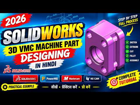
The world of precision engineering is evolving rapidly, and with the release of SolidWorks 2026, designers have more power than ever to create complex industrial components. One of the most critical aspects of modern mechanical design is mastering the creation of Vertical Machining Center (VMC) parts. In this guide, we will break down the full process of designing a robust VMC machine part, focusing on efficiency and accuracy.
The Power of Precision Design
Designing parts for a VMC requires a deep understanding of how material is removed during the machining process. Unlike standard modeling, machine part design demands strict adherence to tolerances and structural integrity. Whether you are a beginner or a professional engineer, mastering the SolidWorks 3D sketch environment is crucial for defining complex paths and wireframe geometries that serve as the backbone of your 3D models.
Why Use 3D Sketching for VMC Parts?
Traditional 2D sketching is often limited to a single plane, which can be restrictive when designing intricate machine components with multiple angles. By utilizing a SolidWorks 3D sketch, designers can manipulate entities in a 3D space without the need for multiple reference planes. This flexibility is essential for creating complex frames, curved piping, or support structures often found in VMC machinery. It streamlines the workflow, reducing the number of features in your design tree and making the model easier to edit later.
Step-by-Step Workflow in SolidWorks 2026
The design process begins with a clear conceptual layout. In our featured tutorial, we walk through the following stages:
- Initial Setup: Choosing the right units and material properties for VMC components.
- Framework Creation: Using the SolidWorks 3D sketch tool to establish the primary skeleton of the part, ensuring all dimensions are fully defined.
- Applying Features: Transforming the sketch into a solid body using Extruded Boss/Base, Swept Boss, and Hole Wizard tools specifically configured for industrial fasteners.
- Refining Geometry: Adding fillets and chamfers to simulate the real-world finish of a machined part.
Conclusion
SolidWorks 2026 offers an intuitive interface that bridges the gap between a digital concept and a physical VMC part. By integrating advanced techniques like the SolidWorks 3D sketch into your routine, you can produce more accurate designs in less time. As you continue to explore the capabilities of this software, remember that the foundation of a great 3D model always starts with a well-planned and executed sketch. Practice these steps to elevate your CAD skills to a professional level.


