
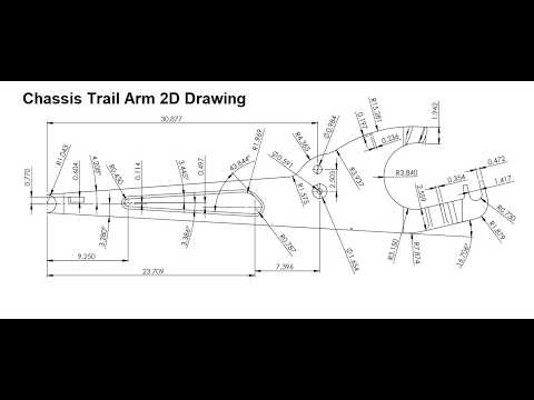
Engineering precision begins with accurate documentation. While 3D modeling is where the creative magic happens, the 2D drawing is the vital "language" that manufacturers use to bring those designs to life. In this SolidWorks 2D tutorial, we explore the systematic process of creating a professional, production-ready drawing for a Chassis Trailing Arm.
Transitioning from 3D to 2D
The journey of a trailing arm starts with a robust 3D model, but the technical drawing is where you define tolerances, material specifications, and critical dimensions. To begin, you must import your part into the SolidWorks drawing environment. Choosing the right sheet format is essential, as it dictates the scale and the amount of information you can clearly display. For a complex component like a chassis trailing arm, an A3 or B-size sheet usually provides enough real estate for detailed views.
Establishing the Layout
The first step in any effective SolidWorks 2D tutorial is setting up your standard views. For a trailing arm, you need a primary front view that shows the overall profile, followed by projected top and side views. These views allow the manufacturer to understand the thickness of the material and the placement of mounting points. Don't forget to include an isometric view in one of the corners; this provides a 3D perspective that helps the machine shop visualize the final product instantly.
Adding Precise Dimensions and Annotations
Once the views are placed, the real work begins: dimensioning. For a chassis component, accuracy is non-negotiable. You must highlight the center-to-center distances between bushings and the exact angles of the arm's geometry. Use the "Smart Dimension" tool to capture lengths, diameters, and hole callouts.
Key elements to include in your drawing: * Centerlines and Center Marks: These are crucial for any circular mounting points. * BOM (Bill of Materials): If your trailing arm is an assembly, a BOM is necessary to list every nut, bolt, and weldment. * Tolerances: Specify how much deviation is allowed to ensure the chassis aligns perfectly during vehicle assembly.
Conclusion
Mastering the art of technical documentation is what separates a hobbyist from a professional engineer. By following this SolidWorks 2D tutorial, you have learned how to take a complex suspension component and translate it into a clear, concise blueprint. Remember, a great drawing doesn't just show what the part looks like—it explains exactly how to build it correctly. Keep practicing these techniques to streamline your design-to-manufacturing workflow.


