
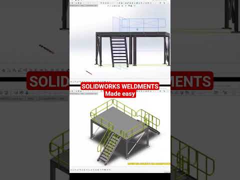
Designing structural frameworks in 3D CAD doesn't have to be a tedious, time-consuming process. Whether you are building custom machinery frames, architectural handrails, or industrial equipment, SolidWorks offers a dedicated feature set to speed up your engineering workflow. That feature set is known as Weldments.
In this quick guide, we’ll break down what this tool is, how it works, and why it is essential for modern CAD designers looking to boost productivity.
What Are Weldments in SolidWorks?
At its core, the Weldments functionality in SolidWorks allows you to design structural frame assemblies as a single multi-body part rather than creating individual components and mating them together in a complex assembly file.
Instead of building each beam or tube separately, you start with a simple 3D sketch acting as the frame's skeleton. From there, you can rapidly apply standardized structural profiles—such as square tubing, I-beams, C-channels, or angle iron—along those sketch paths with just a few clicks.
Key Benefits of Using Structural Frame Tools
Why should you switch from traditional assembly modeling to structural frame modeling? Here are a few game-changing advantages:
- Speed and Efficiency: Creating complex structural frames takes a fraction of the time compared to inserting individual parts and configuring mates.
- Automatic Cut Lists: SolidWorks automatically generates precise, itemized cut lists detailing profile types, lengths, and cut angles for workshop fabrication.
- Easy Corner Treatments: You can effortlessly apply end trims, miter joints, and butt joints to intersecting profiles without manual trimming.
- Integrated Accessories: Adding gussets, end caps, and weld beads directly to your multi-body part is fast and intuitive.
Simple Steps to Get Started
- Draw the Frame Skeleton: Create a 2D or 3D sketch that represents the centerlines of your frame structure.
- Apply Structural Members: Select your desired standard (such as ISO or ANSI Inch), choose a profile type, and apply it to the sketch segments.
- Refine Joints and End Conditions: Choose how your corners intersect, whether mitered or trimmed flush.
- Generate the Cut List: Finalize your design and extract the detailed cut list for purchasing and fabrication.
Conclusion
Mastering Weldments will dramatically reduce your CAD design time and minimize costly errors on the shop floor. Give this powerful toolset a try on your next structural framing project and experience a faster, smarter way to model in SolidWorks!


