
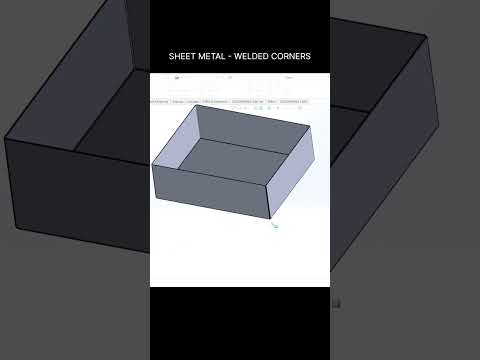
In the world of mechanical design, the difference between a hobbyist project and a professional-grade component often lies in the details. When working with SolidWorks 3D sheet metal, one of the most critical details is how you handle corners. Leaving gaps or unfinished edges in your digital model can lead to manufacturing errors, weak structural integrity, or a lack of aesthetic polish. Today, we are exploring how to use the "Welded Corner" feature to create seamless, professional designs.
The Importance of Seamless Transitions
When you fold a sheet metal part using multiple flanges, the corners naturally create small gaps where the material meets. In a real-world manufacturing scenario, these gaps often need to be closed to ensure the part is airtight, aesthetically pleasing, or structurally sound. By mastering the specialized tools within SolidWorks 3D sheet metal, designers can simulate the actual welding process, providing a much more accurate representation of the final physical product.
Step-by-Step: Using the Welded Corner Tool
The Welded Corner feature is a powerful utility located within the Sheet Metal tab. To use it effectively, follow these steps:
- Prepare your Flanges: Ensure you have created your base and edge flanges first.
- Access the Tool: Select the "Welded Corner" icon from the Sheet Metal toolbar.
- Select the Face: Click on the face of the corner you wish to weld. SolidWorks will automatically identify the adjacent edge and fill the gap with a simulated weld bead.
- Customize the Finish: You can adjust the corner type, choosing between various gap styles or adding a specific radius to the weld bead.
This process ensures that your 3D model accurately reflects how the part will look after it has been handled by a fabrication specialist.
Enhancing Professionalism and Accuracy
Utilizing these advanced features in SolidWorks 3D sheet metal does more than just make your models look "pretty." It significantly improves the quality of your flat patterns and technical drawings. By closing corners properly in the software, you provide clear, unambiguous instructions to the fabrication shop, reducing the risk of misinterpretation during the assembly and welding phases.
Whether you are designing electronics enclosures or heavy-duty industrial brackets, mastering corner treatments is an essential skill for any modern engineer. Start applying these techniques today to elevate your design workflow and produce manufacturing-ready models.


