
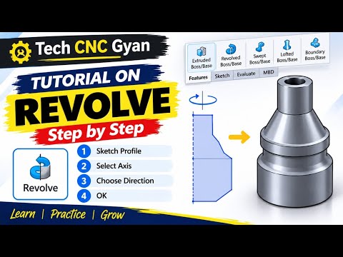
Transitioning from simple flat drawings to complex three-dimensional objects is a crucial milestone for any beginner designer. In the world of SolidWorks 2D CAD, one of the most powerful tools to achieve this transformation efficiently is the Revolve Command. Whether you are designing mechanical shafts, pulleys, or intricate spherical components, mastering the Revolve tool will drastically speed up your modeling workflow.
In this beginner-friendly guide, we will walk you through the fundamentals of converting a basic sketch into a complete 3D solid model using the Revolve feature.
What is the Revolve Command in SolidWorks?
The Revolve command allows you to create 3D features by rotating a closed 2D profile around a defined axis of revolution. Instead of extruding a shape straight out, revolving sweeps the profile along a circular path. This makes it ideal for creating cylindrical, conical, or symmetrical parts with minimal effort.
Step-by-Step Guide: How to Use the Revolve Command
-
Create Your 2D Profile Start by selecting a plane (Front, Top, or Right) and drafting a clean profile in your SolidWorks 2D CAD workspace. Ensure your sketch forms a closed loop, as open contours may lead to thin-feature surfaces rather than solid geometry.
-
Draw an Axis of Revolution Every revolve feature requires a center point to spin around. Add a Construction Line (Centerline) to your sketch precisely where you want the rotational axis to be located.
-
Activate the Revolve Boss/Base Feature Navigate to the Features tab on the top menu bar and click on Revolve Boss/Base. SolidWorks will usually auto-select your centerline as the Axis of Revolution. If it doesn't, simply click on the centerline manually.
-
Define the Angle and Confirm By default, SolidWorks revolves the profile a full 360 degrees. However, you can easily adjust the angle (e.g., 90° or 180°) depending on your design requirements. Review the yellow preview on screen, and click the green checkmark to generate your 3D model.
Final Thoughts
Understanding how to turn a basic SolidWorks 2D CAD sketch into a revolved 3D model is a fundamental skill every engineer and designer should master. By leveraging the Revolve tool, you can cut down design time significantly compared to standard extrusions. Give it a try on your next project!


