
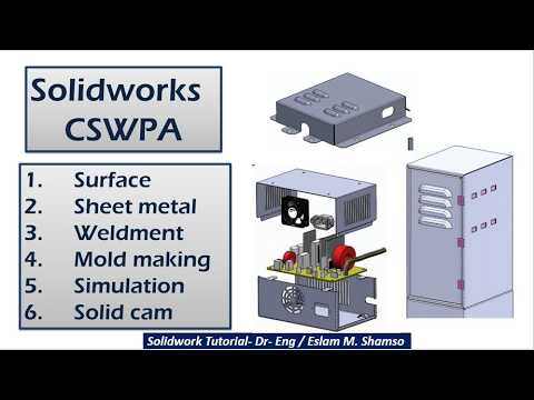
Creating precise 3D models is only half the battle in modern mechanical engineering. To bring your designs to life on the shop floor, translating those models into detailed manufacturing blueprints is essential. Whether you are an engineering student or a practicing designer, mastering the art of a clean SW drawing is critical for seamless production and clear communication across engineering teams.
In this guide, we explore the core principles of engineering assembly drawings and how you can optimize your drafting workflow for maximum clarity.
The Importance of Assembly Drawings in Engineering
An assembly drawing does far more than just showcase a finished 3D model; it serves as a functional guide for manufacturing, quality control, and physical assembly. A high-quality visual blueprint includes:
- Bill of Materials (BOM): A detailed table outlining every part, quantity, and material specification.
- Exploded Views: Clear visual breakdowns illustrating how individual components interlock.
- Balloon Callouts: Numerical identifiers linking physical parts directly to the BOM.
Without these standardized elements, even the most sophisticated CAD designs can result in costly manufacturing errors and assembly confusion.
Essential Tips to Improve Your SW Drawing Workflow
To ensure your final blueprints meet industry standards, consider applying these best practices whenever you create an SW drawing:
- Standardize Projections: Consistently use either First Angle or Third Angle projection based on your regional engineering standards to prevent misinterpretation.
- Utilize Section Views: Leverage cross-sectional and detail views to expose hidden internal mechanisms without cluttering the primary view with excessive hidden lines.
- Optimize Dimensioning: Focus on critical fit dimensions, overall envelope dimensions, and key interface tolerances required for final assembly rather than over-dimensioning individual parts.
- Streamline Annotations: Keep notes concise and organized systematically around the drawing border to maintain clean layout aesthetics.
Elevating Designs from CAD to Simulation
Establishing robust drafting practices early in your design process also simplifies downstream engineering tasks, such as Finite Element Analysis (FEA) and computational simulations in advanced software like ANSYS. When components are properly constrained and documented in your SW drawing, preparing geometry for structural or thermal analysis becomes far more efficient.
Conclusion
Developing professional drafting habits takes time and practice, but the payoff in manufacturing accuracy is immense. By applying these fundamental assembly drawing techniques, you will produce clearer documentation, minimize production delays, and elevate your overall CAD engineering skill set.


