
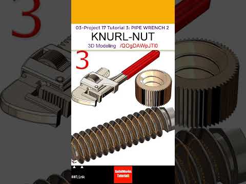
Mastering complex mechanical components is a fundamental step for any CAD designer looking to improve their modeling and tooling skills. In this tutorial, we focus on designing a knurled adjusting nut for a classic pipe wrench assembly. Understanding how to create detailed threaded and textured components is essential not only for standard mechanical design but also for preparing parts in SolidWorks 3D mold design.
Understanding the Geometry of the Knurled Nut
The adjusting nut of a pipe wrench requires both internal threading and an external textured surface (knurling) to allow users to grip and turn it easily. Creating these features accurately ensures that your model translates smoothly into downstream applications, such as computer-aided manufacturing (CAM) or mold creation.
Key modeling steps include: - Base Cylinder Creation: Start by revolving or extruding the main cylindrical body based on the required pipe wrench dimensions. - Internal Threading: Apply standard internal thread profiles to ensure proper engagement with the wrench hook jaw. - Diamond Knurling Pattern: Use a combination of helix curves, cut-sweeps, and circular patterns to build a clean, tactile knurling texture on the outer face.
Bridging Part Modeling and Mold Tooling
When designing components with intricate textures like knurling, tool release and manufacturability become critical considerations. Advanced SolidWorks 3D mold design requires designers to evaluate draft angles, parting lines, and core/cavity splits. A textured surface that looks great in a rendering must still be extractable from a mold cavity without causing clearance issues.
By practicing precise feature creation on small components like this adjusting nut, you build a strong foundation for managing complex split lines and shut-off surfaces in larger tooling projects.
Enhancing Your CAD Workflow
Precision and attention to detail are what differentiate beginner models from professional-grade designs. Integrating these step-by-step techniques into your regular practice will greatly boost your proficiency in SolidWorks 3D mold design and general mechanical drafting.
Whether you are building assemblies for simulation, generating manufacturing drawings, or designing injection molds, mastering individual components like the knurled adjusting nut is a vital step in your journey as a SolidWorks expert.


