
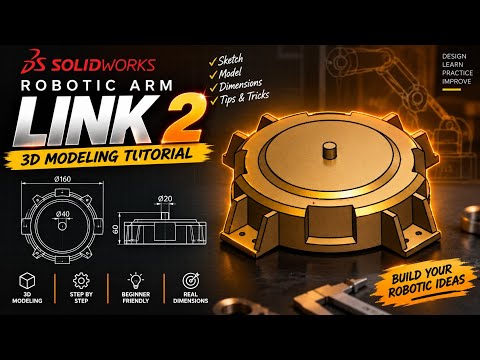
Designing robotics components requires precision, efficiency, and a solid grasp of modern CAD software. Whether you are an engineering student, a hobbyist, or a professional designer, learning how to model mechanical assemblies step-by-step is an essential skill. In this practical SW tutorial, we focus on building "Link 2" of a custom robotic arm assembly from scratch using fundamental 3D modeling tools.
Preparing Your Sketch and Foundation
Before jumping into complex 3D features, every successful CAD model begins with a clean, fully constrained 2D sketch. To construct Link 2 of the robotic arm, you start by establishing key dimensions, centerlines, and geometric relationships. Utilizing parametric design tools allows you to maintain design intent from the start, ensuring that any future adjustments to your robotic arm assembly can be made effortlessly without breaking downstream features.
Converting Sketches into 3D Solid Geometry
Once your base sketch is defined, it is time to give your component volume. In this section of our SW tutorial, we demonstrate how to apply essential Boss Extrude and Cut Extrude features to form the primary structural body and connection joints of Link 2. You will learn how to draft accurate mounting holes for bearings or pins, optimize wall thickness for mechanical stability, and apply strategic fillets to distribute mechanical stress and eliminate sharp edges.
Refining Details for Assembly Integration
The final stage of modeling Link 2 involves fine-tuning the geometry to guarantee seamless integration with adjacent links and actuators. Adding structural chamfers, weight-reduction pocket cuts, and proper material properties ensures your part is ready for real-world simulation or 3D printing. Following a structured SW tutorial gives you the hands-on practice needed to build confidence in mechanical design while mastering industry-standard workflows.
Ready to enhance your 3D modeling skills? Follow our step-by-step video guide to craft Link 2 today and move one step closer to completing your custom robotic arm project!


