
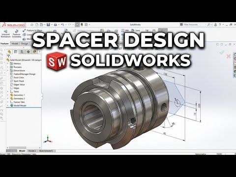
Designing mechanical components requires precision, efficiency, and a solid grasp of CAD software. Whether you are an engineering student or a professional designer, mastering the creation of fundamental parts is the first step toward complex machine design. In this guide, we will walk you through the streamlined process of designing a custom spacer using the industry-standard software, SolidWorks. A spacer might seem like a simple component, but it is an excellent project for practicing core modeling techniques that apply to almost every mechanical assembly.
Starting with the Perfect Sketch
Every great 3D model begins with a clean 2D sketch. To start your spacer, open a new part file and select a primary plane—typically the Top or Front plane—and initialize the Sketch tool. Use the Circle tool to create two concentric circles starting from the origin point. Starting at the origin ensures that your part is perfectly centered, which is a best practice for maintaining symmetry and making future assembly mates much easier to manage.
Defining Precision with Smart Dimensions
A spacer's utility depends entirely on its dimensional accuracy. Use the Smart Dimension tool to define the inner diameter (ID) to fit your bolt or shaft, and the outer diameter (OD) to meet your specific spacing requirements. By defining these parameters clearly, you leverage the powerful parametric engine within SolidWorks, allowing you to update the size of the spacer instantly at any point in the design cycle without having to redraw it. Always ensure your sketch is "Fully Defined" (indicated by the lines turning black) before moving to the 3D phase to prevent accidental geometric shifts.
From 2D Sketch to 3D Geometry
Once your sketch is finalized, navigate to the Features tab and select the "Extruded Boss/Base" command. This is the stage where your flat drawing gains physical volume. Enter the specific thickness or length required for your spacer. A professional tip for beginners is to use the "Mid Plane" extrusion option; this keeps the original sketch plane in the center of the part, which is incredibly helpful when you need to mirror features or add reference geometry later in the design process.
Finalizing the Design
To give your model a professional finish, you may want to add a small chamfer or fillet to the edges. This not only makes the part look more realistic but also replicates real-world manufacturing where sharp edges are removed for safety and ease of assembly. Mastering these fundamental workflows in SolidWorks provides the essential building blocks needed to tackle any 3D modeling challenge with confidence. By following these steps, you ensure your parts are robust, editable, and ready for production.


