
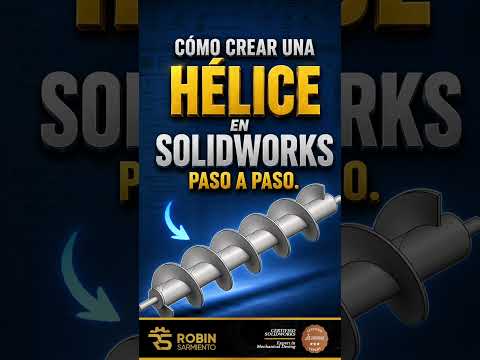
Designing complex 3D components like springs, threads, or custom coils requires precise curve generation. If you want to elevate your mechanical design capabilities, learning how to create a helix in SolidWorks is an essential skill to master. In this guide, we will walk you through the simple step-by-step process of creating a clean, accurate helix curve to enhance your 3D modeling workflow.
Step 1: Create the Base Circle Sketch
Every helix starts with a circular profile that defines its diameter.
- Open a new Part document in SolidWorks.
- Select a plane (such as the Top Plane) and start a new 2D sketch.
- Select the Circle tool and draw a circle starting from the origin.
- Use Smart Dimension to set the exact diameter for your helix.
- Exit the sketch once the dimensions are applied.
Step 2: Insert the Helix/Spiral Feature
Once your base sketch is ready, you can convert the 2D circle into a 3D helical path.
- Navigate to the Features tab on the CommandManager toolbar.
- Click on the Curves drop-down menu and select Helix/Spiral.
- Click on the circle sketch you just created to activate the Helix PropertyManager.
- In the PropertyManager, select how you want to define the helix (e.g., Pitch and Revolution, Height and Pitch, or Height and Revolution).
- Input your specific values for Pitch, Revolutions, and Starting Angle. You can also specify the direction (clockwise or counterclockwise) and add a taper angle if necessary.
- Click the green checkmark to build the 3D helix curve.
Step 3: Sweep a Profile Along the Helix Path
To turn your reference helix curve into a solid 3D object (such as a coil spring or screw thread):
- Create a sketch profile (e.g., a small circle) on a plane perpendicular to the start point of your helix.
- Go to the Features tab and select Swept Boss/Base.
- Set your newly created profile as the Profile and the helix curve as the Path.
- Click OK to complete the solid feature.
Final Thoughts
Creating complex shapes doesn't have to be overwhelming. Mastering fundamental features like helix curves in SolidWorks allows you to design detailed springs, threads, and custom mechanical parts with precision and efficiency. Try experimenting with different pitch and taper settings to expand your CAD modeling toolkit!


