
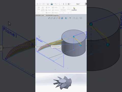
Creating complex, smooth 3D geometries can often feel overwhelming, especially when working with organic shapes or customized product designs. Fortunately, mastering the SolidWorks Loft Surface command is the ultimate key to transforming your sketches into flawless, professional 3D models. Whether you are an aspiring designer or an experienced engineer, understanding how to control lofts will dramatically improve your surfacing workflow.
Understanding Profiles and Connectors
The foundation of any successful loft feature lies in profile selection. Profiles define the cross-sectional shape of your surface at various points. When setting up a loft, always make sure you select corresponding vertices or alignment points across each profile. Misaligned connectors can cause unwanted twists and surface distortion. By taking the time to carefully organize your sketches beforehand, you lay the groundwork for a clean, continuous surface structure.
Utilizing Guide Curves for Ultimate Control
While profiles set the general shape, Guide Curves are what truly give you precision over the final geometry. When working in SolidWorks, you can easily select guide curves directly from the FeatureTree or graphics area to steer the path between your profiles. Guide curves ensure that your surface follows exact design constraints, preventing sagging or unintended bulging. For best results, ensure that your guide curves physically intersect every profile in the loft feature.
Fine-Tuning Start and End Constraints
To achieve professional-grade surface continuity, don't forget to adjust your start and end constraints. Applying options like "Normal to Profile" or "Direction Vector" gives you exact control over how the loft surface emerges from or meets neighboring geometry. Combining these boundary constraints with well-defined guide curves gives your SolidWorks models a smooth, manufacture-ready finish.
Conclusion
By mastering profile alignment, guide curves, and boundary constraints, you will no longer have to struggle with broken or warped surface features. Start applying these simple techniques to your daily design workflow and elevate your 3D modeling capabilities to a professional level!


