
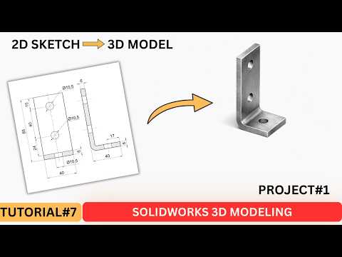
Transitioning from traditional 2D engineering blueprints to fully realized 3D models is an essential skill for modern designers, drafters, and mechanical engineers. Being able to visualize and construct accurate digital prototypes not only speeds up the design process but also minimizes costly manufacturing errors. In this practical guide, we will walk you through transforming a 2D mounting bracket drawing into a precise 3D model using SolidWorks.
Step 1: Setting Up the Base 2D Sketch
Before creating any 3D geometry, you must carefully analyze the dimensions and tolerances on your 2D blueprint. Start by creating a new part file and selecting the most logical base plane—typically the Front or Top plane depending on the component's primary orientation.
Using basic sketch tools such as lines, arcs, and circles, draw the outer boundary of your mounting bracket. Always remember to apply geometric relations (like horizontal, vertical, and concentric) alongside Smart Dimensions to ensure your sketch becomes fully defined before moving on to the next phase.
Step 2: Adding Volume with Boss-Extrude
Once your 2D profile is fully constrained, it is time to give it depth. Navigate to the Features tab and select the Boss-Extrude command. Input the exact depth or thickness indicated on your technical drawing.
By converting your flat 2D sketch into a solid 3D base, you create the primary body of the mounting bracket. This foundational feature serves as the anchor for all subsequent modifications, such as mounting holes, slots, or cutouts.
Step 3: Removing Material Using Extruded Cut
Most mechanical components require mounting holes or weight-reduction pockets. To create these features, select the surface face where the openings belong and start a new sketch. Draw the required hole profiles based on your reference drawing dimensions.
Apply the Extruded Cut tool to remove material through the solid body. You can choose options like "Through All" or specify an exact blind depth depending on the design requirements.
Step 4: Refining and Verifying the Final Model
To complete your mounting bracket, apply finishing touches like fillets or chamfers to remove sharp edges and reduce stress concentrations. Finally, double-check all model dimensions against your original 2D drawing to verify total accuracy.
Mastering these essential workflows in SolidWorks empowers you to take on increasingly complex CAD projects with speed and confidence. Practice building this mounting bracket model today to sharpen your 3D design toolkit!


