
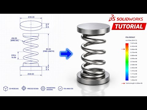
Helical compression springs are among the most fundamental mechanical components used across automotive suspensions, consumer electronics, and industrial machinery. Designing these dynamic parts requires a blend of precise parametric geometry and reliable structural validation, which is where SolidWorks excels as an industry-standard design platform.
In this guide, we break down the end-to-end process of creating a custom helical compression spring and running a Finite Element Analysis (FEA) study to evaluate its real-world performance.
Step 1: 3D Modeling the Helical Spring
Creating an accurate spring geometry requires a structured parametric approach:
- Define the Base Profile: Sketch a circle representing the mean coil diameter on your primary plane.
- Generate the Helix: Navigate to the Curves menu and select Helix/Spiral. Define the pitch, revolution count, and total height according to your engineering specifications.
- Draw the Cross-Section: Create a sketch representing the spring wire diameter at the starting node of the helix.
- Apply the Swept Boss/Base: Sweep the circular profile along the helical path to generate the solid spring body.
- Ground the Ends: Compression springs typically feature flat ends for proper seating. Use reference planes and a Cut-Extrude feature at both ends to create flat, parallel bearing surfaces.
Step 2: Running FEA Simulation for Structural Validation
After completing the 3D model, activate the SolidWorks Simulation add-in to analyze structural behavior under compressive loading.
- Material Assignment: Assign a suitable spring material, such as ASTM A228 (Music Wire) or Stainless Steel, to ensure accurate mechanical property data.
- Fixtures and Loads: Apply a fixed geometry constraint to the bottom flat surface. Next, apply a compressive axial force or linear displacement to the top flat surface.
- Meshing and Study Execution: Create a refined curvature-based mesh to accurately capture localized stress along the helical curves, then run the static analysis.
Evaluating Results and Design Optimization
Once the study completes, review the Von Mises stress plot and total displacement results. Pay close attention to the inner coil surfaces, where shear stresses tend to peak. Compare the maximum stress against the material's yield strength to verify your factor of safety.
Leveraging SolidWorks for both parametric modeling and simulation allows engineers to optimize spring designs rapidly, lowering prototyping costs and ensuring structural reliability.


