
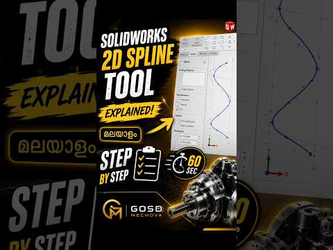
When creating complex, organic shapes in SolidWorks, mastering the 2D Spline tool is essential. While traditional sketching tools like lines and arcs are great for standard geometric features, splines give you the flexibility to design smooth, flowing curves effortlessly. If you have ever found curvature controls confusing, this guide breaks down how simple it truly is to use.
What is the 2D Spline Tool?
The 2D Spline tool in SolidWorks allows designers to generate smooth, continuous curves that pass through a series of specified points. Unlike standard arcs with a constant radius, a spline dynamically adjusts its curvature based on control points and handles. This makes it the ideal feature for modeling aerodynamic components, ergonomic product grips, and sleek consumer electronics.
How to Create a 2D Spline Step-by-Step
Getting started with splines is straightforward. Here is how you can draw one in your active sketch:
- Open a Sketch: Select your desired plane (Front, Top, or Right) and start a new sketch.
- Activate the Spline Tool: Click on the Spline icon on the Sketch toolbar, or navigate to
Tools > Sketch Entities > Spline. - Place Your Control Points: Click on the graphics area to place your starting point, add intermediate points along your curve path, and double-click to finish.
- Adjust Curvature Handles: Click on any point along the spline to reveal its tangency handles. Simply drag these handles to modify the curve's direction, magnitude, and angle.
Pro Tips for Better Spline Control
- Minimize Control Points: Using fewer points creates a smoother, more continuous curve that is much easier to edit.
- Apply Tangent Relations: You can add geometric constraints (such as Tangent or Equal Curvature) between splines and adjacent lines for smooth surface transitions.
- Dimension the Handles: Fully define your sketch by adding smart dimensions to the length and angle of the spline handles.
Conclusion
Designing smooth, organic geometry does not have to be complicated. By following these basic principles, you can elevate your SolidWorks sketching skills and construct precise, high-quality models with confidence. Try experimenting with the 2D Spline tool in your next design project!


