
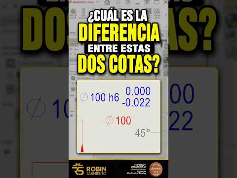
When reading or creating engineering drawings, subtle details can mean the difference between a perfectly fitted mechanical assembly and a costly manufacturing mistake. One of the most common points of confusion for CAD designers involves interpreting drawing callouts—specifically, understanding the functional difference between basic nominal dimensions and specific fit tolerances like H6.
Standard Dimensions vs. Fit Tolerances
At first glance, two dimension callouts on a technical drawing might look nearly identical. However, a basic dimension simply indicates the nominal target size, whereas an alphanumeric callout like H6 introduces a standardized ISO fit tolerance.
When detailing parts in SolidWorks, choosing between a standard dimension and an explicit fit tolerance completely changes how the machinist interprets your design intent. A simple dimension tells the shop floor the general target size, while an H6 designation specifies exact upper and lower deviation limits required for precise mechanical mating.
What Does an H6 Tolerance Actually Mean?
The letter and number combination in a tolerance callout provides critical manufacturing data: - The Capital "H": Indicates a hole-basis tolerance system where the lower deviation of the tolerance zone is zero. - The IT Grade "6": Specifies the International Tolerance grade, which dictates the overall tightness of the tolerance band.
An H6 tolerance implies a high-precision fit commonly used for shaft-and-hole assemblies, such as locating pins and bearing housings. Interpreting this correctly ensures that parts function properly without requiring unnecessary and expensive tight-tolerance machining across the entire component.
Streamlining Precision Drawings in SolidWorks
Modern CAD software makes it seamless to apply and display these ISO fits directly on your models and 2D prints. By utilizing the built-in detailing tools within SolidWorks, engineers can automatically populate tolerance values and assign H6 limits to hole features. This eliminates manual calculation errors and ensures clear communication between the design team and the shop floor.
Understanding how to read and apply these tolerances empowers you to design higher-quality parts while keeping manufacturing costs under control.


