
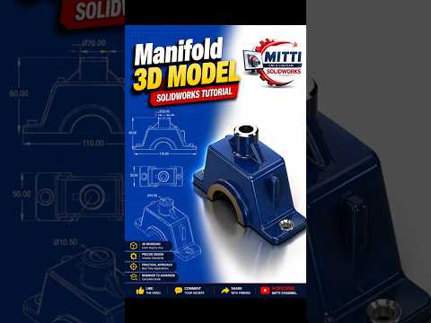
Designing mechanical components requires precision, especially when dealing with complex internal channels like manifolds. If you are looking to sharpen your CAD skills, tackling a manifold is one of the best ways to test your spatial reasoning and feature mastery. In this guide, we will walk you through the essential workflow for creating an accurate manifold 3D model using SolidWorks.
Understanding the Geometry of a Manifold
Before diving into the software, it is crucial to analyze the functional requirements of a manifold. Manifolds distribute fluid or gas through multiple intersecting channels, which means your design must maintain consistent wall thickness, accurate port alignments, and smooth internal flow paths.
Instead of getting overwhelmed by the overall shape, break the component down into primary geometric blocks, connecting pipes, and mounting flanges. Building your model systematically from the core outward makes the overall process far more manageable.
Key Features Used in the Modeling Process
To construct a robust manifold model in SolidWorks, you will utilize a combination of standard 3D design features:
- Base Boss/Extrude: Establish the main outer body block using precise dimensions from your reference drawing.
- Reference Planes: Set up angled offset planes to create secondary ports and non-standard connection points accurately.
- Extruded & Swept Cuts: Carve out internal passages, ensuring all intersecting channels align perfectly for optimal flow.
- Fillets and Chamfers: Apply realistic radii to internal corners to reduce stress concentrations and improve manufacturing feasibility.
Best Practices for Clean CAD Architecture
Maintaining an organized feature tree is vital when working on intricate mechanical parts. Always fully define your 2D sketches with proper geometric relations and smart dimensions before applying 3D features. Additionally, naming your key features in the design tree will make future edits much easier if design specifications change down the line.
Level Up Your Mechanical Design Skills
Whether you are a beginner looking to build core competencies or an experienced engineer refining your workflow, practicing complex parametric modeling in SolidWorks is an excellent way to advance your career. Follow along with our complete step-by-step tutorial video to build this manifold model from scratch and elevate your CAD capabilities today!


