
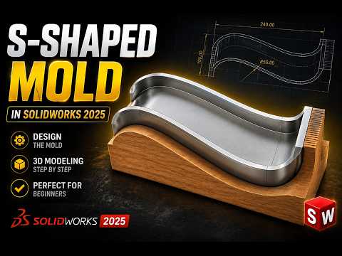
Designing complex curved parts doesn't have to be overwhelming, especially when you are just starting your 3D modeling journey. Learning how to build smooth, organic geometries like an S-shaped mold is one of the best ways to sharpen your skills. In this beginner-friendly guide, we will walk you through the core steps required to design an S-shaped mold efficiently using SolidWorks.
Step 1: Crafting the S-Curve Sketch
The foundation of any solid mold design begins with a clean, well-constrained sketch. Start by opening a new part file and selecting your working plane (typically the Front Plane). Use the Spline or Tangent Arc tools to draw your custom S-shape. Pay close attention to curvature continuity to ensure smooth transitions throughout the shape. Once your profile is ready, use the Boss-Extrude feature to give your S-shaped geometry its initial 3D thickness.
Step 2: Building the Core and Cavity
To turn your base geometry into a functional mold, you need to generate separate core and cavity blocks. By leveraging the built-in Mold Tools in SolidWorks, you can split your design into two distinct halves with minimal effort: 1. Parting Line: Run a quick draft analysis to define where the mold block will separate. 2. Shut-Off & Parting Surfaces: Automatically patch any open voids and extend a parting surface outward from the parting line. 3. Tooling Split: Create a sketch for the outer block dimensions, then execute the tooling split to generate the top (cavity) and bottom (core) components.
Step 3: Optimizing for Manufacturability
A great CAD model must also be practical for manufacturing. Ensure your mold features adequate Draft Angles (usually 1° to 3°) along vertical faces so the final part ejects smoothly. In addition, apply generous fillets to sharp corners to reduce structural stress and promote optimal material flow during the molding process.
Final Thoughts
Creating complex organic forms becomes much simpler once you understand the basic mold-building workflow. SolidWorks offers intuitive surface and tooling tools that empower both beginners and experienced engineers to bring intricate concepts to life. Give this S-shaped mold tutorial a try today and take your CAD design capabilities to the next level!


