
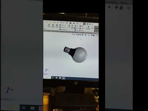
Designing everyday objects is one of the best ways to sharpen your CAD skills. Among classic practice models, a 3D light bulb is a fantastic project because it combines organic curves, precise helical threads, and detailed interior geometry. In this guide, you’ll learn how to leverage SolidWorks to model a realistic light bulb from scratch.
Step 1: Sketching the Glass Profile and Base
To begin, start a new part file and select the Front Plane. You will create a 2D sketch representing half of the bulb's outer profile, including the rounded glass dome and the metallic base contour.
Use the Revolve Boss/Base feature around a central construction line to convert your 2D outline into a smooth 3D solid body. Once the revolve is complete, apply a thin Shell feature to hollow out the glass bulb section, giving it realistic wall thickness.
Step 2: Creating the Screw Base Threads
The screw thread at the base gives the light bulb its iconic, functional look. To model this: 1. Select the cylindrical face of the base and sketch a circle matching its outer diameter. 2. Insert a Helix/Spiral curve to define the pitch and total revolutions for the thread pathway. 3. Draw the thread profile (a small circle or rounded rectangle) on a plane perpendicular to the start of the helix path. 4. Apply the Swept Boss/Base feature, using your profile and the helix curve.
Mastering swept features alongside helical curves is essential for tackling complex mechanical designs in SolidWorks.
Step 3: Adding Filaments and Applying Appearances
Inside the bulb, create the filament assembly using 3D sketches combined with the Sweep tool. Sketch thin support wires and a coiled central filament to add an extra level of detail and realism to your design.
Finally, apply realistic materials and appearances to your model. Assign a clear glass material to the upper dome, polished aluminum or brass to the metallic thread base, and a dark black plastic appearance to the bottom contact point.
Final Thoughts
Creating a light bulb is an excellent exercise for both beginners and intermediate CAD designers. By practicing tools like Revolve, Helix, and Sweep, you will significantly improve your overall design workflow. Open SolidWorks today and start bringing your illuminated ideas to life!


