
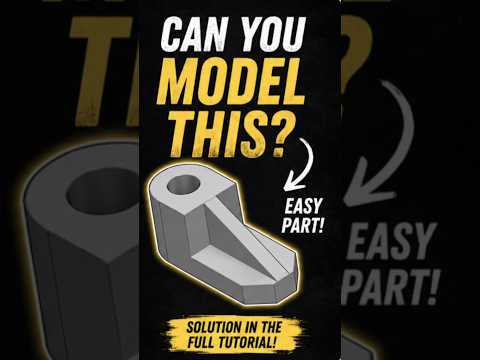
Transitioning from a 2D engineering drawing to a fully realized 3D component is one of the most vital skills for any CAD designer or mechanical engineer. Whether you are a beginner looking to build confidence or an experienced user sharpening your workflow, practicing with real-world mechanical parts is the most effective way to improve. In this guide, we will walk through the step-by-step process of modeling a simple mechanical bracket in SolidWorks using standard technical blueprints.
Step 1: Analyzing the 2D Engineering Blueprint
Before creating any 3D features, it is crucial to carefully study the original 2D blueprint. Take note of key dimensions, hole locations, wall thicknesses, and overall symmetry. Identifying primary references early on allows you to select the optimal sketching plane—such as the Top or Front plane—and utilize time-saving tools like symmetry constraints and offset entities.
Step 2: Building the Base Sketch and Extrusion
Once you understand the blueprint dimensions, start by drafting the main profile of the mechanical bracket: 1. Open a new part document and select your starting reference plane. 2. Sketch the primary outline using fundamental line and arc tools. 3. Fully define your sketch by applying precise geometric relations and smart dimensions. 4. Apply a Boss-Extrude feature to turn your 2D sketch into a solid 3D base body.
Step 3: Adding Cutouts, Holes, and Fillets
With the main body created, focus on the secondary features that complete the bracket's functionality: - Extruded Cuts: Create secondary sketches on the bracket faces to cut out material according to the blueprint specifications. - Hole Wizard: Quickly generate accurate mounting holes for standard bolts or mechanical fasteners. - Fillets and Chamfers: Apply smooth radii to internal and external edges to eliminate sharp corners, enhancing structural integrity and aesthetics.
Conclusion
By breaking down technical drawings into simple geometric shapes, mastering parametric modeling becomes much more manageable. Utilizing software like SolidWorks enables you to rapidly convert complex engineering concepts into precise, production-ready models. Keep practicing with diverse 2D blueprints to continuously elevate your 3D design skills!


