
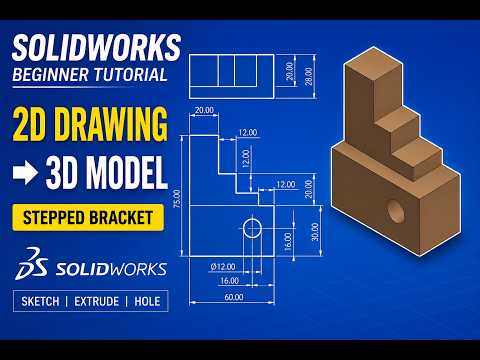
Transitioning from a 2D engineering blueprint to a fully realized 3D model is one of the most fundamental skills every aspiring mechanical designer needs to master. If you are just starting your CAD journey, learning how to interpret dimensions and translate them into digital features within SolidWorks is the ultimate way to build a solid foundation.
In this beginner-friendly guide, we walk through the essential process of creating a Stepped Mechanical Bracket directly from a technical 2D drawing.
Step 1: Analyzing the 2D Drawing
Before jumping straight into sketching, spend a few moments studying the 2D engineering print. Identify the primary base feature, key dimensions, hole locations, and stepped elevations. Understanding how these geometric features relate to one another will help you choose the best reference plane and design strategy from the start.
Step 2: Creating the Base Profile
Start by selecting the appropriate reference plane (such as the Front or Top Plane) to draw the primary profile: 1. Main Sketch: Draft the basic outline of the bracket using standard line tools, ensuring key geometric constraints (horizontal, vertical, perpendicular) are automatically or manually applied. 2. Dimensioning: Apply precise values matching the 2D drawing. Fully defining your sketch at this stage prevents unwanted shifts later in the design process. 3. Boss Extrude: Extrude the main body to the specified base thickness.
Step 3: Building the Stepped Features and Cuts
The defining characteristic of a stepped bracket is its multi-level geometry: * Select the upper face of your base extrusion to sketch the next level of the bracket. * Leverage core SolidWorks features like Extruded Boss/Base to build up the elevated steps, and Extruded Cut to form internal slots or mounting holes. * Keep your feature tree organized so that future design modifications remain simple and error-free.
Step 4: Finishing Touches
Once the main solid geometry is established, apply finishing touches such as edge fillets or chamfers as specified in the drawing notes. Adding these aesthetic and functional details at the end of your workflow ensures clean parametric management.
Conclusion
Modeling a stepped mechanical bracket is an excellent project for honing fundamental parametric modeling skills in SolidWorks. By practicing how to systematically read 2D drawings and translate them into 3D features, you will quickly build the confidence needed to tackle more complex engineering challenges.


