
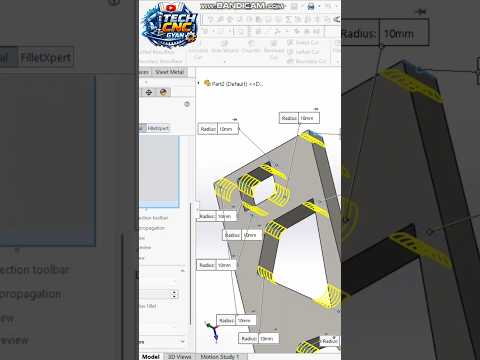
When creating engineered parts or consumer products, sharp edges are rarely desirable. Whether you are aiming to improve structural integrity or simply create a sleek, polished look, mastering the Fillet tool is an essential skill for any beginner working with SolidWorks 3D CAD.
In this guide, we will break down what the Fillet feature is, why it is crucial for 3D design, and how you can seamlessly apply it to your models.
What is the Fillet Tool in SolidWorks?
The Fillet tool creates a rounded internal or external face on a 3D model. In practical manufacturing, rounding sharp corners reduces stress concentrations on a mechanical component, making it stronger and less prone to failure. Additionally, it improves safety by removing sharp edges and gives your design a professionally finished appearance.
Key Types of Fillets
Understanding the different options within the Fillet command helps you choose the right approach for your project:
- Constant Size Fillet: Applies a uniform radius across the selected edges. This is the most common and straightforward type used in basic modeling.
- Variable Size Fillet: Allows you to specify different radii at various points along a single edge, creating a smooth transition from a small curve to a larger one.
- Face Fillet: Blends non-adjacent or adjacent faces together, which is ideal when edge selection alone is insufficient.
- Full Round Fillet: Creates a continuous fillet across three adjacent faces, effectively rounding off an entire side of a solid body.
Step-by-Step: How to Apply a Fillet
Applying a fillet is quick once you understand the basic workflow:
- Activate the Command: Navigate to the Features tab on the command manager and click Fillet.
- Select Fillet Type: Choose the appropriate fillet type (e.g., Constant Size) from the PropertyManager.
- Choose Items to Fillet: Select the specific edges, faces, or loops on your model where you want the rounded edge applied.
- Set Parameters: Input your desired radius value. Enable Full Preview so you can see how the geometry will change in real time.
- Confirm: Click the green checkmark to execute the feature.
Best Practices for Beginner Modelers
To keep your SolidWorks 3D CAD models clean and easy to edit later, keep these simple tips in mind:
- Fillet Last: Place your fillet features near the end of your FeatureManager design tree. Adding rounded edges early can complicate sketch references and cut extrudes.
- Group Similar Fillets: Apply fillets with identical radius values within the same feature operation to minimize tree clutter.
- Watch for Intersections: Ensure your chosen radius does not exceed the dimensions of neighboring geometry, which can cause feature rebuild errors.
By incorporating these tips into your workflow, you will elevate your modeling technique and unlock the full potential of your SolidWorks 3D CAD projects. Practice applying different fillet types today to see the difference in your 3D models!


