
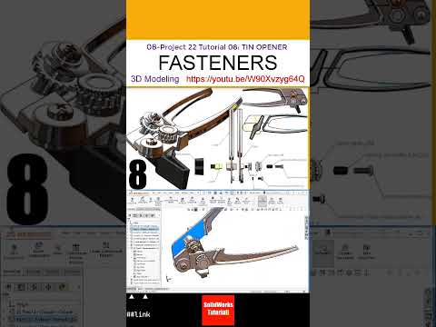
Designing complex mechanical devices requires a clear understanding of component relationships and mechanical motion. In this practical guide, we take a deep dive into building a fully functional tin opener using a SolidWorks 3D assembly. Whether you are an engineering student or a seasoned designer, mastering multi-part assemblies and dynamic mates is essential for creating accurate digital prototypes.
Placing Standard Hardware and Components
Every reliable mechanical design starts with precise alignment. In this project, the initial focus begins with positioning the structural body of the tin opener and systematically adding standard hardware. You will learn how to efficiently insert essential components such as pins, washers, and threaded screws into your workspace. Applying proper concentric, coincident, and parallel mates ensures that each fastener seats perfectly within its designated slot, laying a solid foundation for the overall mechanism.
Mastering Gear Mates for Realistic Functionality
The true power of a SolidWorks 3D assembly lies in its ability to simulate real-world mechanical motion. To make the tin opener operational, implementing mechanical mates—specifically gear mates—is critical. By accurately defining the gear ratios and rotational axes between the drive handle, spur gears, and cutting wheel, you ensure smooth, synchronized movement. This step bridges the gap between static 3D modeling and dynamic kinematic analysis.
Simulating Motion and Finalizing the Project
Once all components and mates are correctly established, it is time to bring the model to life. Utilizing SolidWorks Motion features allows you to animate the mechanism and verify that the handle rotation drives the cutting blade without physical interference. Testing motion not only validates your constraint logic but also provides a professional visual trailer suitable for portfolio showcases or project presentations.
By mastering these techniques, you will significantly elevate your skills in SolidWorks 3D assembly design, preparing you to tackle far more intricate mechanical engineering projects with confidence.


