
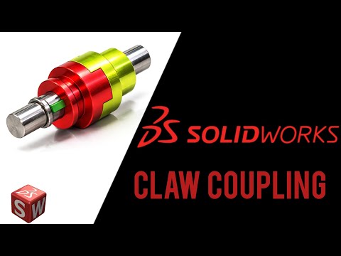
Mechanical design can often seem intimidating for beginners, but mastering essential components like a claw coupling is one of the best ways to build confidence in 3D CAD modeling. Whether you are an engineering student or an aspiring CAD technician, learning how to transform ideas into a precise SolidWorks Drawing is a foundational skill that will set your work apart.
In this guide, we break down the core process of modeling a mechanical claw coupling step-by-step so you can master key features in SolidWorks with ease.
What is a Claw Coupling?
A claw coupling (often referred to as a jaw coupling) is a power transmission component used to connect two rotating shafts. It efficiently transmits torque while accommodating minor shaft misalignments and dampening system vibrations. Because of its distinct interlocking teeth, modeling this component provides an excellent exercise for practicing rotational symmetry and precise feature creation.
Key Steps to Model a Claw Coupling
- Establish the Base Hub: Start a new sketch on the Front Plane. Draw a circular profile representing the outer diameter of the hub, then use the Extruded Boss/Base tool to create the base cylinder.
- Form the First Claw: Sketch the cross-section of a single claw tooth on the outer face of the hub. Use geometric relations and exact dimensions to maintain symmetry before extruding the feature.
- Apply a Circular Pattern: Instead of drawing each tooth manually, use the Circular Pattern tool. Select the initial claw tooth feature and rotate it around the central axis to generate the remaining teeth instantly.
- Create the Center Bore and Keyway: Draw a central circle on the hub face and use the Extruded Cut feature to create the shaft hole. Add a keyway profile to ensure the coupling can lock onto a drive shaft.
- Apply Fillets and Chamfers: Add small fillets to the internal corners to reduce stress concentrations, and apply chamfers along the outer edges for a clean, professional finish.
Transitioning from 3D Model to Production
Creating a 3D model is only part of the design workflow. Once your model is complete, generating a clean 2D SolidWorks Drawing is essential for real-world manufacturing. Adding standard orthographic projections, detailed dimensions, and section views ensures that machinists can accurately manufacture your component.
Conclusion
Building fundamental components is the fastest route to CAD proficiency. By taking the time to practice creating a accurate SolidWorks Drawing for parts like claw couplings, you build the core skills required to tackle far more complex engineering projects in the future.


