
Designing structural frames, steel assemblies, and complex tubing manually can consume hours of tedious CAD modeling. Fortunately, working with SolidWorks 3D weldments streamlines this entire process, allowing engineers and designers to build robust structural frames in a fraction of the time.
Whether you are designing industrial machinery, equipment bases, or custom metal frameworks, mastering the weldment workflow is an essential skill. Here is how you can leverage this powerful feature to speed up your design pipeline.
Step 1: Lay the Foundation with a Sketch
The weldment workflow begins with wireframe geometry. Instead of creating multiple individual part files, you start by defining a frame skeleton using 2D or 3D sketches. A 3D sketch gives you the flexibility to define complex spatial frameworks effortlessly, establishing the exact paths your structural profiles will follow without creating multiple reference planes.
Step 2: Apply Structural Members
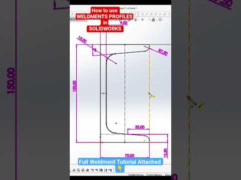
Once your skeletal framework is ready, activate the Weldments feature and choose your structural profiles. SolidWorks comes equipped with a comprehensive library of standard shapes, including square tubing, angle iron, C-channels, and pipe profiles.
When building structural models, utilizing SolidWorks 3D weldments ensures that profile cross-sections automatically align and extrude along your sketch lines. This single-part multi-body approach saves you from spending hours applying mates in traditional assemblies.
Step 3: Refine Corners and Trim Intersections
Clean joinery is crucial for accurate structural modeling. SolidWorks automatically handles corner treatments, letting you choose between mitered joints, end-butt joints, or custom corner gaps. If structural members overlap, the built-in Trim/Extend tool instantly cleans up intersecting geometry to ensure your model is ready for fabrication.
Step 4: Automate Cut Lists and Documentation
One of the biggest advantages of working with SolidWorks 3D weldments is the automated Cut List functionality. Instead of manually calculating profile lengths, SolidWorks automatically tracks, groups, and quantifies identical structural members. You can effortlessly generate accurate cut lists directly on your manufacturing drawings, drastically reducing human error.
Accelerate Your CAD Workflow Today
By shifting from traditional multi-part modeling to a weldment-driven approach, you eliminate unnecessary file clutter and streamline structural revisions. Start incorporating weldments into your daily CAD workflow to experience faster modeling, seamless drawing creation, and enhanced productivity.


