
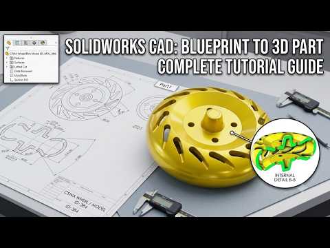
Are you looking to elevate your computer-aided design skills or prepare for the CSWA (Certified SolidWorks Associate) exam? Transforming flat technical blueprints into dynamic, high-precision parametric models is a fundamental skill every mechanical engineer and designer must master. Learning how to translate a SolidWorks 2D drawing into a complex 3D model is essential for building real-world mechanical components like slotted wheel rims.
Understanding Blueprint Interpretation for CSWA Success
When preparing for design certifications, interpreting a standard SolidWorks 2D drawing accurately is half the battle. Technical drawings convey critical geometric data, dimensions, reference planes, and design intent.
In this slotted wheel CAD project, the process begins by analyzing the blueprint's reference dimensions: overall hub diameter, rim thickness, bolt patterns, and slot angles. By breaking down complex features into basic geometric primitives, you can establish a clean design intent that makes editing and adjusting the model effortless later on.
Key Steps to Build the Slotted Wheel
To construct an accurate 3D rim from a 2D engineering drawing, follow this structured workflow:
- Establish the Base Profile: Start by creating a precise sketch of the wheel’s cross-sectional profile using centerline construction lines. Use the Revolve Boss/Base feature to generate the main wheel body efficiently.
- Cut the Slotted Features: Create a sketch on the front face of the wheel to define the unique slot or spoke profile. Apply an Extruded Cut feature through the rim wall.
- Utilize Symmetry: Save time by using the Circular Pattern tool to replicate the slot feature evenly around the central axis of the wheel.
- Apply Finishing Touches: Add strategic fillets and chamfers to relieve stress concentrations on sharp edges, giving the wheel a realistic, finished look.
- Verify Mass Properties: Assign a material (such as an Aluminum Alloy) to the part. Checking the mass, center of mass, and surface area is a key requirement for answering CSWA examination questions accurately.
Elevate Your CAD Modeling Skills
Whether you are an engineering student preparing for your certification or a beginner looking to sharpen your parametric modeling skills, hands-on practice is key. Working through a project from a SolidWorks 2D drawing to a completed 3D assembly enhances your spatial awareness and speeds up your design workflow. Grab your blueprint, open SolidWorks, and start modeling your wheel today!


