
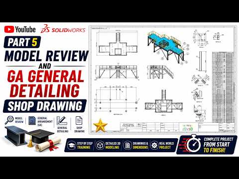
Taking a steel structure project from initial concept to the fabrication shop floor requires precision, clarity, and an efficient technical workflow. While building a robust model is essential, the true test of structural engineering lies in converting 3D geometry into clear General Arrangement (GA) drawings and precise shop drawings for manufacturing.
Conducting a Thorough 3D Model Review
Before generating any 2D drawings, a comprehensive review of your digital structure is non-negotiable. Inspecting connection details, structural member alignments, and potential interference issues early saves costly shop floor re-works. When working with SolidWorks 3D weldments, establishing standardized structural profiles and clean sketch layouts ensures that your framework is fully defined and structurally sound.
During the model review phase, pay close attention to: - Structural member intersections and trim/extend conditions. - Standardized gusset plates, base plates, and bolt hole clearances. - Correct orientation and alignment of structural shapes (I-beams, channels, and hollow sections).
Bridging the Gap: GA Detailing and Shop Drawings
Once your model passes inspection, the next step is translating it into actionable fabrication documentation. General Arrangement (GA) drawings serve as the master roadmap for site installation, outlining overall dimensions, grid lines, and main assembly locations.
Simultaneously, structural detailers must generate individual shop drawings for each member and connection. Utilizing SolidWorks 3D weldments makes this transition remarkably smooth. Because the software automatically tracks structural members and generates accurate cut lists, creating detailed views of individual parts, plates, and sub-assemblies becomes significantly faster and less prone to manual error.
Best Practices for Seamless Fabrication Drawings
To maximize efficiency when preparing your final drawing packages, consider the following best practices:
- Leverage Automatic Cut Lists: Ensure your weldment cut lists are properly updated so that lengths, cut angles, and quantities populate accurately in your drawing tables.
- Standardize Drawing Templates: Pre-configure your title blocks, bill of materials (BOM) tables, and callout styles to maintain consistency across all project sheets.
- Clear Annotation: Clearly indicate field welds versus shop welds, surface treatments, and assembly marks to eliminate guesswork for fabricators.
Mastering the complete pipeline—from reviewing robust SolidWorks 3D weldments to publishing detailed production drawings—is the key to delivering professional structural engineering projects efficiently and accurately.


