
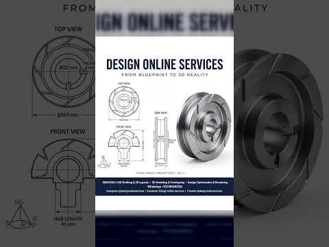
Mechanical components like pulleys play a vital role in power transmission across modern industrial machinery. Designing these elements requires precision, strong drafting fundamentals, and modern parametric tools. Whether you are transitioning from traditional 2D mechanical drafting to modern modeling standards, learning to design a classic V-belt pulley using SolidWorks 3D CAD is an essential milestone for any aspiring mechanical engineer or designer.
Demystifying Mechanical Drafting: Third-Angle Projection
Before jumping directly into three-dimensional space, every solid engineering design begins with a clear 2D technical layout. Utilizing standard third-angle projection allows designers to accurately map out dimensions, centerlines, section views, and groove angles required for a functional V-belt pulley. Understanding these orthographic views ensures that key mechanical features—such as keyways, shaft bores, wall thicknesses, and hub dimensions—are precisely defined before constructing geometry.
Step-by-Step Modeling of a V-Belt Pulley
Translating a standard 2D engineering blueprint into a fully realized solid model is straightforward when leveraging SolidWorks 3D CAD. The modeling workflow typically follows a structured engineering approach:
- Revolved Base Geometry: Sketching half of the pulley cross-section along a central axis and executing a 360-degree revolve to form the core solid body.
- Precision V-Grooves: Creating defined groove sketches that conform to standard industrial belt profiles and utilizing revolved cuts around the main axis.
- Shaft Bore & Keyway: Adding the central mounting hole and creating a keyway cut-extrude feature designed to transmit rotational torque reliably.
- Edge Dress-up Features: Applying appropriate fillets and chamfers to relieve internal stresses and ensure modern manufacturing feasibility.
Why Practice Real-World CAD Projects?
Bridging the gap between 2D technical drawings and SolidWorks 3D CAD modeling sharpens your spatial awareness and overall workflow efficiency. Practicing on fundamental mechanical components like pulleys, shafts, and couplings equips engineers with the practical problem-solving capabilities required in the automotive, aerospace, and industrial equipment industries.
Mastering these core drafting and parametric modeling techniques will ensure your designs are not only visually impressive but also fully accurate and production-ready.


