
Mastering the Art of 3D Modeling from Technical Drawings
In modern mechanical design, transitioning from traditional SolidWorks 2D drafting to precise 3D modeling is an essential skill for engineers, draftspersons, and CAD enthusiasts. Creating a functional 3D part from an engineering blueprint requires a strong grasp of orthographic projections, tolerances, and spatial reasoning.
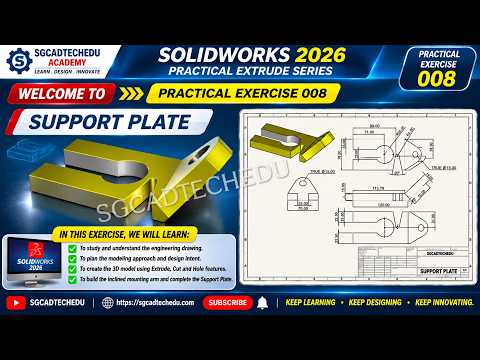
In this modeling exercise, we explore how to interpret a technical drawing and build a robust Support Plate 3D model using the latest features in SOLIDWORKS 2026.
Step-by-Step Guide: Building the Support Plate
To transform a flat drawing into a fully realized 3D component, follow this structured workflow:
1. Analyze the 2D Blueprint
Start by carefully examining the technical print. Understanding the key dimensions and geometric constraints defined during SolidWorks 2D drafting ensures that your final 3D model remains accurate and fully parametric. Identify the main base feature and secondary operations like cutouts or mounting holes.
2. Create the Primary Base Sketch
Select the appropriate reference plane (typically the Front or Top Plane) and draw the main outline of the Support Plate. Utilize geometric relations (such as horizontal, vertical, and concentric constraints) alongside Smart Dimensions to ensure your sketch is fully defined.
3. Apply the Base Feature
Use the Extruded Boss/Base command to convert your 2D sketch into a solid 3D body, extruding it to the exact thickness specified in the blueprint.
4. Add Detailed Features and Cutouts
Create secondary sketches on the faces of your 3D body to add critical details such as bolt holes, slots, or central cutouts. Use Extruded Cut to pierce through the plate as required by the design specifications.
5. Final Finishing Touches
Apply fillets and chamfers to smooth sharp edges and match the engineering requirements. Assign proper materials to calculate mass properties and verify design accuracy.
Why Bridging 2D and 3D Design Matters
While 3D modeling is ideal for visualization and simulation, standard technical drawings remain the universal language of manufacturing. Developing a strong foundation in SolidWorks 2D drafting allows designers to effortlessly interpret shop floor blueprints, eliminate modeling errors, and streamline the product development process.
Whether you are preparing for SOLIDWORKS certification or sharpening your modeling speed, practicing with real-world exercises like this Support Plate is one of the most effective ways to boost your CAD proficiency.


